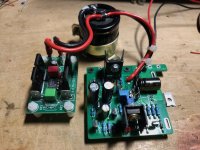
Red LED flashing, if input voltage is lower than set output, is not a primary function, just a neat side effect. With output set to 17.5 V, some load and input dropped to 17 V, red LED should start to slowly flash or “wink at you” or at least be lit continuously.
Green LED indicates power on.
Green LED indicates power on.
Expensive but good design. Let's not debate the PCB though 🙂 The design is so good it would serve quite well as high(er) power LDO PSU for class D amplifiers so with rectifiers and bulk caps onboard. Of course with Phoenix MKDSN or heavier screw type connectors.
For anyone in NL, B, F or D: I have PCBs left. Just send a PM.
For anyone in NL, B, F or D: I have PCBs left. Just send a PM.
Attachments
Last edited:
It would be way more usable/versatile with normal square/rectangular shape and as a complete stand alone PSU. Also it lacks mounting holes and one of the 2 existing mounting holes interferes with a heatsink. Opinion/taste/preference, nothing more. I really like the performance!
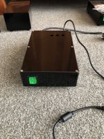
I just built it as exercise as I (like usual) just had finished an LDO 5A PSU for class D MA12070 amplifiers. Also functioning quite well but with higher dropout voltage. Case is heatsink.
I just built it as exercise as I (like usual) just had finished an LDO 5A PSU for class D MA12070 amplifiers. Also functioning quite well but with higher dropout voltage. Case is heatsink.
Attachments
Last edited:
Yes, I agree on that. Maybe with next version.t would be way more usable/versatile with normal square/rectangular shape and as a complete stand alone PSU
Like you I am used to criticism. It can make stuff better. It is not meant negatively as the design does what it is supposed to do for the intended goal.
For general/broader use outside class A it could be a compact one board design to fit in existing power amplifiers. As these tend to be quite small size would be a design parameter. As these amplifiers are not converting energy to useless heat continuously heatsink requirements would be lower too. Probably chassis mounting to bottom or a back side heatsink would be enough.
The 3 second non regulated period makes the design unusable for streamers or SBCs as these generally are allergic to overvoltages. Maybe an enable/disable jumper?
Last edited:
Does anyone have a working LTSpice simulation of the regulator? Tombo said earlier his were "not ready for posting", whatever that means.
I tried, but in mine, the output voltage is like the input voltage, no regulation and bad ripple.
I tried, but in mine, the output voltage is like the input voltage, no regulation and bad ripple.
You probably don’t need simulation but you do seem to need non virtual trouble shooting. An assembly error? Part value error?
Mine did not regulate either as I soldered in both power transistors in mirror. Oops.
Mine did not regulate either as I soldered in both power transistors in mirror. Oops.
You have that problem with simulation or with built regulator?I tried, but in mine, the output voltage is like the input voltage, no regulation and bad ripple.
What would you like to accomplish with simulation? I may already know the answer if there is a question. There is a large performance difference between simulation and the real circuit.
Design goal to make an add-on regulator that will survive power-on with any large capacitance at the output is a reason for that 3s unregulated period. With complete design on one board, output capacitance can be small and regulation can be used from the first milliseconds. Such was R21 design up to revision 1.3, but it couldn’t unconditionally survive any output capacitance.The 3 second non regulated period makes the design unusable for streamers or SBCs as these generally are allergic to overvoltages. Maybe an enable/disable jumper?
@jean-paul @tombo56 I have not built the regulator, but typically I like to be able to simulate to have a working example to compare to when I build the real thing.
I did this e.g. for Jan Didden HV regulator and it worked like a charm (I did not need to debug, because the real one worked well too, as the sim did).
Of course sim is only sim and people like it or not. I like to see the sim work before I invest in parts and labour.
I did this e.g. for Jan Didden HV regulator and it worked like a charm (I did not need to debug, because the real one worked well too, as the sim did).
Of course sim is only sim and people like it or not. I like to see the sim work before I invest in parts and labour.
One would assume the designer has simulated or (scary) tested and measured the design in real life. It does not sound trustful to want to simulate an existing and tested design and assuming the need to debug. Relevant data to reproduce a good working and performing copy is in post #1.
Last edited:
Well, OK. 😎I like to see the sim work before I invest in parts and labour.
However, I prefer to see circuit working in the real life, as many fine working simulations have no chance to actually work IRL.
I have a question for @tombo56.
I use your R21 voltage regulator for the PSU of my FW F4 balanced mono blocks.
Thank you for this great design!
Everything went well during construction and commissioning, the regulators work without any problems.
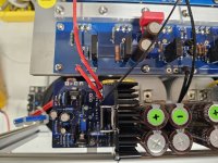
Now I just have to decide on a final connection for the ground of the regulators.
Normally I would connect these directly to the amplifier boards.
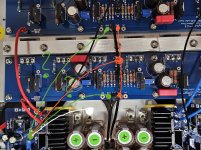
But because I use two amplifier boards due to the balanced configuration, I'm not sure which one (green).
Or in the middle of an additional ground connection between the boards (red).
Or perhaps to the ground connection of the capacitors behind the regulator?
Or a different position?
Thank you in advance for your help!
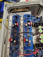
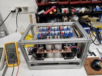
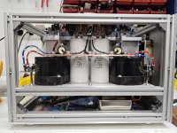


Never thought to use 2020 extrusion for an amp case! Would make for a heavy, but solid build!
Would love to see more pics of your build when you're done

Would love to see more pics of your build when you're done

Have a look at the F4 Building thread:
https://www.diyaudio.com/community/...ing-the-pass-f4-amplifier.234355/post-7728683
https://www.diyaudio.com/community/...ing-the-pass-f4-amplifier.234355/post-7728683
Grounding wires from both regulators should be connected, with shortest path, to the common ground between two final PS output capacitors -> white line on the first pic.Now I just have to decide on a final connection for the ground of the regulators.
BTW, great amplifier build.
Hi, any pics of your setup? ThanksTime to bring this thread back to the right track, my experience with the R21 modules.
To start with, the setup:
Six fully separate power supplies, where 300VA transformers charge capacitors with 0.1F each via 0R1 resistors. The diodes have snubbers. The DC of +- 30V feed six P3A amplifiers (Rod Elliott) in its original versions except for the high frequency branch, where the VAS stage got a five-transistor current mirror and emitter degeneration for the differential pair. The drivers were selected for high efficiency, low mechanical loss, and low distortion (coming from 18Sound: 15" in a closed box, Accuton 173Nd and a large Mundorf AMT). The digital data from a PC go via a Dante network into a HD2, which provides FIR filtering with a linear phase down to 20Hz.
Up to now, the sound of this setup was pleasant to listen to, but at larger volumes many recordings, especially from the progressive rock genre, produce fatigue after a while. Vocals (e.g., the marvelous Dorothea Mields, whom we heard live in concert) had some kind of unnatural sharpness, therefore, room for improvements,
For fitting the four modules into the casing, one of the transformers and its capacitor bank had to leave and where replaced by four R21 modules. The output voltages were set to 26V (30V is the input from the remaining capacitor bank). For getting an AB comparison, one channel was changed and could be compared to the unmodified one:
The unmodified channel had a noticeable brightness in the mids and highs relative to the R21-channel. My wife confirmed this impression without knowing, what I have changed. Furthermore, the sound stage seemed to be a bit more flat with less separation into the stage. So a good incentive to modify the other channel as well.
Wow! The brightness at louder volumes has reduced significantly. Three, four dB louder than before, no problem! Since my wife and me are quite sensitive to distortion, this mod was not the cheapest one (this was removing the screen of the XLR cables from pin 1), but definitely worth it!
Fazit: A simple amplifier such as the P3A (which suffers obviously from a low PSRR) benefits a lot from a ripple-free DC, so go for it.
@tombo56: My sincere thanks for elaborating these modules and providing the Gerber files! I really appreciate this
- Home
- Amplifiers
- Power Supplies
- An arguably better replacement for the resistor in a CRC power supply - R21 PS module
