All is well, thank you.
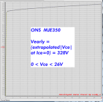
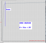
KSA1381 will be available in a month at Mouser (you should order now). If you can’t wait, TTA004 is excellent replacement, if not even better. In that case, go with TTC004 as well. MJE350 is not suitable replacement. It’s not only about allowed Vce but how little Ic changes due Vce variation.
For SQP120N10-09_GE3, R7 should be changed to 3K3.
In case of any dilemma or trouble during build, just ask.
Good morning jean-paul.
Not yet as I don't need different power supply ATM. Projects are brewing but it is still not clear what will be needed.
If you will go for own PCB design, just take care of separate power tracks and Kelvin connection for voltage reference and error amplifier and performance will be excellent. We can discuss small modifications by PM if you decide to go that route.
Last edited:
MJE350 is not suitable replacement [for KSA1381]. It’s not only about allowed Vce but how little Ic changes due Vce variation.
Here are curve tracer plots of KSA1381 and also of MJE350, measured on transistors I bought from Mouser, using the "LockyZ" instrument. The knee in the curve, where constant current behavior begins, is much better in the blue than in the green. Early voltage is better too.
_
Attachments
I encourage you to acquire a curve tracer and an fT meter of your own, they will boost your productivity as a designer, enormously. I've been making this recommendation a lot lately; for example
_
Here is a sample of the owner's manual and user's guide:
You'll need to get a curve tracer and an fT meter so you can correlate SPICE results vs. real measurements on real transistors purchased in the real world from (it is hoped!) non counterfeit sellers. I was lucky enough to find a "BK Precision 530" fT meter at an amateur radio hobbyist site; there aren't many offered for sale but if you can find one, they are excellent.
_
Here is a sample of the owner's manual and user's guide:
Attachments
Oh, I’m encouraged enough 🙂 and there is a nice list of equipment I would very much like to have, but budget has its limits. I must dedicate larger part for the actual builds.
Aside from used BK devices and LockyZ's tracer, do you or anybody else have some recommendations for a viable curve tracer and a means to measure Ft? Older test gear can become a hobby and time sink unto itself. May as well design and build something from scratch in a lot of cases.I encourage you to acquire a curve tracer and an fT meter of your own, they will boost your productivity as a designer, enormously.
Peak Atlas sells a nice curve tracing device, but it's limited.
It's certainly possible to use something like a nanoVNA with the right bias system to measure Ft. Some conversions may be needed, plus you'd need a suitable test fixture.
The ultimate would be finding a software app that would take these measurements and create SPICE models...
For DIY, I think that best way would be to use solution by mbrennwa - software that controls two programmable power supplies. I already have one suitable Riden PS.
https://www.diyaudio.com/community/...cer-using-programmable-power-supplies.344199/
https://pypsucurvetrace.readthedocs.io/en/latest/
https://www.diyaudio.com/community/...cer-using-programmable-power-supplies.344199/
https://pypsucurvetrace.readthedocs.io/en/latest/
Six or seven years ago, I purchased a Syscomp CTR-101 curve tracer. I never could get it to plot smooth curves or to make repeatable measurements: I would trace the same transistor five times, and get five different results. But maybe I was operating it incorrectly, or maybe my unit was defective. I never debugged the problem; I just moved on to using other curve tracers. Here's the sales brochure if you want to explore further.
_
_
Attachments
Thank you both. I will investigate further.
I already own the Peak Atlas DCA75. It works great, but is limited in voltage and current.
I also have the curve tracer adaptor for the Analog Discovery. It also does the job and also is limited in voltage and current. I've considered adding a more robust voltage capability for this by adding a high voltage opamp, but again I'd be diving into the test equipment hobby rather than working on audio gear. Perhaps that's what's required.
Making a SPICE model is still kind of challenging. You can purchase SpiceMod from Intusoft that lets you build a model from a manufacturer's data sheet. That's obviously not the same as using your own measured data. I suppose if I was any kind of mid 21st century modern electrical engineer, I'd write my own application that extracts device parameters from measurements and builds a SPICE model. But, I am not that. I just want to satisfy my circuit curiosity and build audio gear that works well for me.
Maybe just building prototypes using different devices may still be the way to go from a pragmatic sense. Like to compare the use of a KSA1381 versus an MJE350. But, that doesn't really feel like the best way to do things, but it may be practical.
Sorry to derail the thread...
Tombo, I apologize if this has been answered earlier the thread, but would there be a recommended value for the two Caps (C1 > R21 > C2) if starting with a fresh new build? I'm looking at a single rail supply with rectified voltage around 45-50Vdc and 2A Iq for a single-ended SIT amp.
No detailed guidelines were given except that large C2 is not required but doesn’t hurt either.
For C1 we want reasonably low ripple. At 2A load, 22mF would provide some 760 mVpp ripple and that’s good.
Output capacitor (C2) can be small as regulators don’t require anything special for stability, but larger capacitors provide better transient response on high dynamic load. So, 470 uF is minimum and several mF (2200 – 4700 uF) is enough. I like there (for looks and performance) Kemet ALC10S slit-foil 10.000 uF 63V or 80V, available at Mouser.
thanks Tombo! I’ve got the initial parts ordered and will report back with any other questions.
Ha, ha, yes, black sleeve with golden letters always looks nice.Looks?!?!?
Regulators work with small output capacitors. Positive regulator works even without any output capacitor, on condition that constant load of >50 mA is present. Here is its response on 20 kHz, 5A peak transient load with no capacitor. Blue trace is current through 85 mΩ resistor and yellow is output voltage.BTW it works fine with 220 uF at the output.
However, capacitors larger than 220 – 470 uF, show positive difference when regulator is tested with square wave 5 -10 A loads. Differences are still in the mV range, but are there. With several mF capacitor, actual load from amplifier will modulate regulator output in uV range.
Tombo,For C1 we want reasonably low ripple. At 2A load, 22mF would provide some 760 mVpp ripple and that’s good.
I'm planning to use two R21_P in the PSU of my FW F3 build. I have some Cornell Dubilier 380LX183M063A082 capacitors that I'm looking to use in this PSU. Do you think these caps would be fit for the C1 position of the PSU?
Thanks.
- Home
- Amplifiers
- Power Supplies
- An arguably better replacement for the resistor in a CRC power supply - R21 PS module


