The Forum discussion thread linked below, might be helpful:
Ordering PCBs online (using Gerber files): A walkthrough. --- featuring the fab "JLCPCB"
AmyAlice Gerber files are attached to post #1 of this thread
Ordering PCBs online (using Gerber files): A walkthrough. --- featuring the fab "JLCPCB"
AmyAlice Gerber files are attached to post #1 of this thread
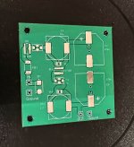
Forgot to write here 😅 Works as intended, awesome for smps powered devices round the house 🙂 Smaller footprint than original, added led for flair. Will increase footprint size a bit for some components for ease of hand soldering.


When you place the two inductors next to each other they couple (like a transformer). Even though "K" is low, it still effects the filter function. You can demonstrate this for yourself in LTSpice.
In ham radio land, the inductors of cascaded filters are either compartmentalized, or placed at right angles.
In ham radio land, the inductors of cascaded filters are either compartmentalized, or placed at right angles.
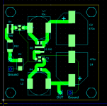
Distance between inductors is the same as in OG board. Works the same as OG board, only smaller footprint and more tidy tracing.
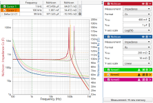
You can only tell if it works better, worse, or the same if you run the filter through a spectrum analyzer and measure the results. I have measured the coupling factor and it is ~=0.08. This can mean a difference of almost 10dB less attenuation in the stopband.
You could unsolder one of the inductors, rotate it 180 degrees, and solder it back again. (You've just swapped the "phase dots" of the transformer.) Now any magnetic coupling which might exist, produces the opposite phase electrical behavior. If magnetic coupling exists to a significant degree, you'll see an electrical difference before/after rotating.
If you have built OG board, measure it on spectrum analyzer. Same distance on my board.
That being said, i don't mind redesigning it when you publish data here (already have for custom spacing in my router).
That being said, i don't mind redesigning it when you publish data here (already have for custom spacing in my router).
Here is a graph of the coupling between two closely placed inductors (those Amy recommends). Is it a "game-breaker"? No, but it is worthy of comment:

Could you show final schematics of Amylice alternative with common mode filter?View attachment 1246797
View attachment 1246798
View attachment 1246795
I tested the discrete component filter last night and it worked great .😛
Purple is the input,Yellow is the output.
Thx noviygera, i don't mind sharing gerbers if Mark is ok with it. It has the same components he uses, and is tested. I made a revision as well so it's easy to hand solder.
I would love to see a JPG of your board layout, top and bottom. If @Mark Johnson is in agreement, of course.
Sure, just create a new Forum discussion thread for your new PCB, so all technical support questions about the new PCB will be directed to you. Once the thread is created I will link to it from post #1 here.
I have been using the AmyAlice with my ACP+ and ACAMini combine and have been very happy with what it has done. I was using the excellent SMPS DC Filter P089ZB, but when I changed it out for the AmyAlice I noticed, what I would call a drop in the noise floor. The power supply noise that was getting through the P089ZB was possibly masking some of the low level music. The change for me is as if there is a little more dynamics to the music.
You milage may vary, but it is will worth the effort to give the AmyAlice a try.
Mark, Thank you very much for the AmyAlice filer
You milage may vary, but it is will worth the effort to give the AmyAlice a try.
Mark, Thank you very much for the AmyAlice filer
- Home
- Amplifiers
- Power Supplies
- AmyAlice: DC filter for SMPS, using 2 feedthru capacitors + SMD assembly. max 3A & max 48V