
Wow, that's an impressively tight fit!! I wonder: was some of it custom-made using a 3D printer?
In any case, congratulations and powerful admirations.
In any case, congratulations and powerful admirations.
Thanks,
yes all housing parts are 3D printed and have melted M3 bushes (hope this is the right word for this).
yes all housing parts are 3D printed and have melted M3 bushes (hope this is the right word for this).
Mark: Is the maximum 3 Amp current rating of the design the average current or the peak current?
To all who are tempted -- It's a great project, even if you only want to learn manual SMD soldering and don't use the output (leave out the big inductors). I've done 11, and have 7 of them earmarked for specific uses, four likely to be installed in the coming weeks. Will report.
Skip
Skip
Components might be the limiting factor, but also consider PCB trace widths.
The PCB trace widths appear to be 80 mils. According to https://www.4pcb.com/trace-width-calculator.html
an 80 mil with 1oz copper will carry 4 amps.
The PCB trace widths appear to be 80 mils. According to https://www.4pcb.com/trace-width-calculator.html
an 80 mil with 1oz copper will carry 4 amps.
As posted the designer said 3A and for sure - given he is quite a serious person - there is, as in every serious project, a safety margin re component's choice, various tolerances, of course PCB traces etc.
My understanding is the official (and absolutely safe) answer is 3A max... Up to you how far you want to gamble.
My understanding is the official (and absolutely safe) answer is 3A max... Up to you how far you want to gamble.
I wouldn't run the board beyond 3.0 amperes peak, myself. I also wouldn't run the board beyond 3.0 amperes average. I also wouldn't run the board beyond 3.0 amperes RMS.
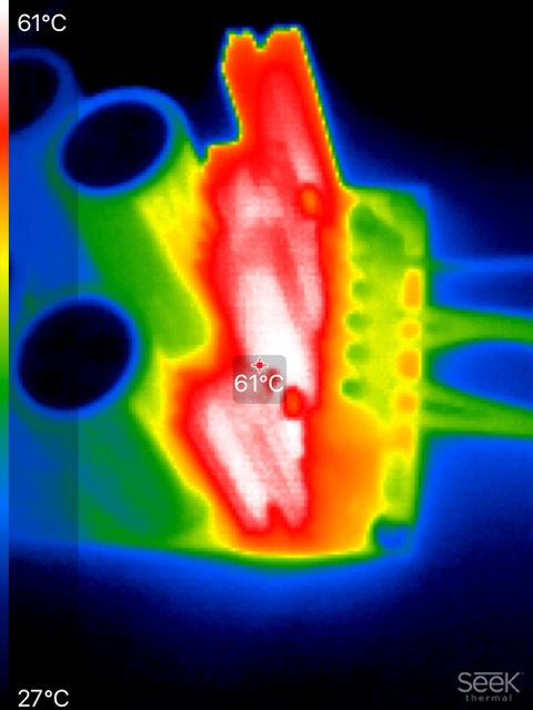
But it's your board, use it however you wish and find out whether it survives or dies. Maybe infrared photography (random example below) might be a fun thing to explore.
If the peak current is a pulse 100 nanoseconds wide and 3.1 amperes tall ... maybe your board will survive.
If the peak current is a pulse 100 nanoseconds wide and 500 amperes tall ... maybe your board won't survive.
Now I've gone through my sound check list and it definitely sounds better!
For some reason, LF has also woken up also compared to PO89ZB.
My speakers have "disappeared" even more!
Thanks!
For some reason, LF has also woken up also compared to PO89ZB.
My speakers have "disappeared" even more!
Thanks!
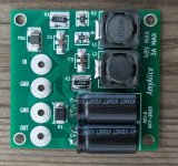
I ordered a pair of PO89ZB from the store, but took a try at replacing Amy's through-hole electrolytic capacitors with surface mount. I have my toaster-oven reflow machine so it's not a hassle. Here are two screen-shots:
Attachments
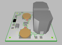

Previously I measured the ESR of the thru-hole Kemet caps in the AmyAlice parts list, along with a couple of possible replacements that were even better. My measured ESR for the Kemet thru-hole capacitor was 45 milliohms. But when I scan DigiKey's list of surface mount electrolytic caps, 470uF at 50V, the best one (least ESR) in the entire table has an ESR of 73 milliohms. So your all-SMD filter's noise attenuation won't be quite as good as the SMD+THT AmyAlice. And you'll pay significantly more money, because high-capacitance, 50 volt electrolytic caps are a lot more expensive in SMD than in thru hole. Price difference was one of the reasons why I chose non-SMD electrolytics for the original AmyAlice.
(Also I worry that those green traces are awfully narrow to be carrying the full 3.0 ampere continuous DC current rating of AmyAlice)
(Also I worry that those green traces are awfully narrow to be carrying the full 3.0 ampere continuous DC current rating of AmyAlice)
Last edited:
I can always shoot some "holes" in there for the Kemet caps (which I already have).
Not worrying about the trace thickness in this application as these will be used to see if I can calm down some switchers for low power operations.
My version of Ultiboard is 12.0 -- so I had to create many of the parts from scratch.
Not worrying about the trace thickness in this application as these will be used to see if I can calm down some switchers for low power operations.
My version of Ultiboard is 12.0 -- so I had to create many of the parts from scratch.
- Home
- Amplifiers
- Power Supplies
- AmyAlice: DC filter for SMPS, using 2 feedthru capacitors + SMD assembly. max 3A & max 48V