Parts shown on
https://www.firstwatt.com/pdf/art_acp.pdf
are correct.
Therefore R16 and R17 are 33.2 Ohm.
The RCA connectors are RCJ-04X where "X" is either 1, 2, 3, or 4, depending on colour.
R22 is for the operation of the LED light. If omitted the LED will not turn on but the rest of the ACP+ will still be fully functional. The schematic shows 7.5K, but the value is not critical. Any value between 7.5K and 24K will work. The lower the resistor value, the brighter the light.
Thanks Ben thats all clear
one more ques if you can please for the C3 1000uf gold I ordered
EEU-FM1V102 (35V 1000uf) according to the BOM in the file, but they dont look "gold" ... are they good to use, if not can you point me to the right parts for that thanks so much
one more ques if you can please for the C3 1000uf gold I ordered
EEU-FM1V102 (35V 1000uf) according to the BOM in the file, but they dont look "gold" ... are they good to use, if not can you point me to the right parts for that thanks so much
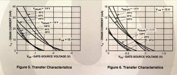
Transfer Characteristics - J113
Would someone help me understand these Performance Characteristics charts for the J113 please?
When I measure Idss (Vgs at 0V, Vds at 16V), it is 11.2mA.
That must have something to do with one of these lines (for Vds at 15V) but what?
I suppose I am asking what is Vgs(off)? Why does it vary?
Would someone help me understand these Performance Characteristics charts for the J113 please?
When I measure Idss (Vgs at 0V, Vds at 16V), it is 11.2mA.
That must have something to do with one of these lines (for Vds at 15V) but what?
I suppose I am asking what is Vgs(off)? Why does it vary?
Attachments
So I decided to focus on just the right channel for now. I have R4 at 21.2 ohms and 199mv across it for 9.4ish milliamps. Now I'm trying to sort out R7 to get the desired 4.5v from DC1 to ground. I've gone up to 110k, and I still have well over 9v. Is something else wrong, or should I keep increasing R7?
DC1 to ground should be around 11V. You do not need to mess around with R7.
Voltage across R15 should be 4.5V or so.
Voltage across R15 should be 4.5V or so.
Parts shown on
https://www.firstwatt.com/pdf/art_acp.pdf
are correct.
Therefore R16 and R17 are 33.2 Ohm.
The RCA connectors are RCJ-04X where "X" is either 1, 2, 3, or 4, depending on colour.
R22 is for the operation of the LED light. If omitted the LED will not turn on but the rest of the ACP+ will still be fully functional. The schematic shows 7.5K, but the value is not critical. Any value between 7.5K and 24K will work. The lower the resistor value, the brighter the light.
I am glad you noticed this and pointed out how to populate R22. I was just packing the last of the first batch of kits when I realized that R22 was not included in the BOM we used to put it together as it did not appear in the BOM from Nelson's original article which we used as the reference. It only appears on the schematic.
It goes to show you that it pays to carefully read BOTH the schematic and the BOM folks. 😉
--Tom
DC1 to ground should be around 11V. You do not need to mess around with R7.
Voltage across R15 should be 4.5V or so.
I don't know at what point I confused myself with looking for 4.5v at DC1 instead of R15, but that was really messing with me.
Either way, thank you for your help. I finally finished it up earlier this evening, and heard some music through it for the first time.
Now I just need to build myself an enclosure for it and my ACA.
You have to build to find out.
Probably need a source resistor for Q6 to reduce DC drift.
Patrick
Probably need a source resistor for Q6 to reduce DC drift.
Patrick
thank you very much Patrick. Add the Q6 source resistor and adjust the gain to about 16db.
Will try to layout the PCB and try it and then feedback.
Will try to layout the PCB and try it and then feedback.
Attachments
Last edited:
Contribute one datapoint and solution
humming, if removed rca in, right channel buzz terribly.
DC voltage: 24.9v
R12/13 drop: 333mV r14/15 drop 166mV
PSU - triad 24v 0.5A (one in Nelson’s article, reterminated with 5.5 2.5 barrel.
PSU said 0.4A max, and measured at max.
Replaced with Meanwell 5A adapter and hum gone.
Measurements shows 1A /25W sufficient.
Voltage across R12 = 325mV on both sides
underplate pcb => yes, I have one
"screwing thin wire to pot nut and solder it to gnd" by pot nut you mean from one of the 4 nuts that hold the screws in place that connect the pcb to the ground plate => screw wire in one and solder to gnd? Did that but doesn't help with the humming
I've been loving this as a headphone amp for the last year but I'm tiring of having a seperate dac and the ACP+ on my desk.
Has anyone bundled this up with a nice DIY DAC into a nice package? I'm on the novice side of things but am ready for a new project. thanks!
Has anyone bundled this up with a nice DIY DAC into a nice package? I'm on the novice side of things but am ready for a new project. thanks!
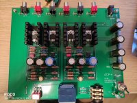
I finished putting everything tgt, and I chked the Voltages, and realised ont he Left channel its 11Vs the the DC1 side of R12 and R13 and on the Right channel it measured 18 ish V which obviously is not whats expected, So I went ahead and plugged in headphones and the right channel is just buzz noise and left works perfectly fine. is there anyway to trouble shoot it? I have checked the solder joints at the bottom , and on the front side i attached a picture , looks identical to the left so im not sure how to go about fixing it. Appreciate the help!
Attachments
What is the voltage across R15? It should be about 4.5V.
And what is the voltage across R4, and what is the value of R4 (125 Ohm as specified)?
And what is the voltage across R4, and what is the value of R4 (125 Ohm as specified)?
I finished putting everything tgt, and I chked the Voltages, and realised ont he Left channel its 11Vs the the DC1 side of R12 and R13 and on the Right channel it measured 18 ish V which obviously is not whats expected, So I went ahead and plugged in headphones and the right channel is just buzz noise and left works perfectly fine. is there anyway to trouble shoot it? I have checked the solder joints at the bottom , and on the front side i attached a picture , looks identical to the left so im not sure how to go about fixing it. Appreciate the help!
I ran into a similar problem with my build. Based on help I got here in this thread I ended up lowering the value of R4 significantly. The goal is to have 10mA of current across R4, so you may need to try a few values in that position to get as close to that as you can.
What is the voltage across R15? It should be about 4.5V.
And what is the voltage across R4, and what is the value of R4 (125 Ohm as specified)?
R15 on the left channel I got 4.65 V and on the right it's 4.3V
And R4 I'm using 124ohms resistors. Both channels measures around 11 to 11.9 depending on which side of the resistor... Also these measurements are taken by fixing the black pole on the GND at top right and red pole on the resistor either side... Hope that's the right way to do it...
Was just reading a few posts earlier, which talked about a similar issue. So I have change the value of the R4 to achieve 10mA. So can I ask a dumb ques how to measure that? I'm not sure if I'm doing the right thing. But I flip my DDM to Amp and 200m , black pole on ground and red to R4 , left channel give 20 and right gives 11...
Measure the voltage across R4 then apply Ohm's law. I = V/R. For example 1 volt across R4 with a 100 ohm resistor = 10 mA At least that's how I do it. I'm sure we'll both learn something if I'm wrong!
[error correction -- I originally wrote mV instead of mA--sorry]
[error correction -- I originally wrote mV instead of mA--sorry]
Last edited:
- Home
- Amplifiers
- Pass Labs
- Amp Camp Pre+Headphone Amp - ACP+