R15 on the left channel I got 4.65 V and on the right it's 4.3V
And R4 I'm using 124ohms resistors. Both channels measures around 11 to 11.9 depending on which side of the resistor... Also these measurements are taken by fixing the black pole on the GND at top right and red pole on the resistor either side... Hope that's the right way to do it...
Measuring across a resistor means a probe on either side so please remeasure.
Ladwig - That’s not how you measure current with a DMM... in our case, with the components all installed we have to measure the DC voltage across the resistor and then apply a little math to determine the current.
As Audiobear mentions, I=V/R, so measure the voltage drop across R4 and divide by that resistor value to get current.
EDIT: lol.. lots of people typing at the same time! 🙂 🙂 🙂
As Audiobear mentions, I=V/R, so measure the voltage drop across R4 and divide by that resistor value to get current.
EDIT: lol.. lots of people typing at the same time! 🙂 🙂 🙂
thanks for the help, so i measured the DC across R15 left 4.65 and right 4.3, and R4 left 0.9 and R4 right 0.55
so if im using 124 ohms in R4, its 0.9 / 124 = 7.25 mA and 0.55 / 124 = 4.45 mA?
if i have done this right, my ques is how come its so different between the 2 channels given they are identical parts left and right? and to fix this do i have to assume 0.9 and 0.55 stay the same and get 90 ohms and 55 ohms resistor for R4?
The J113 are not identical. That's the issue when buying them from normal distributorship. (We are working on addressing this...) The Jfets have a very wide range of Idss that they can fall into and still be considered J113.
The math isn't quite as simple as that as you are reading the current that those specific transistors are pulling over the 125R resistors, but the good news is you'll be able to swap in different resistors and keep applying that formula until you get the requisite 10mA current. I'd get a metal film resistor assortment pack and a few alligator clips and clip in until it's right. You can do this with the existing 125R in parallel if you want.
The math isn't quite as simple as that as you are reading the current that those specific transistors are pulling over the 125R resistors, but the good news is you'll be able to swap in different resistors and keep applying that formula until you get the requisite 10mA current. I'd get a metal film resistor assortment pack and a few alligator clips and clip in until it's right. You can do this with the existing 125R in parallel if you want.
The J113 (Q3) seems to have large manufacturing tolerance. One solution is to test in-circuit as you are doing. The other method is to test using a test rig (very simple diy circuit).
From your results, you need to decrease value of R4. The design current is 10mA. The right channel right now is too low for Q1 to function properly, thus only 4.3V across R15, which is not enough to get Q6 to also function properly.
So you need some resistors to try in the R4 position. To increase the current, you need to decrease the resistor value from what you are currently using. Perhaps start at 50 Ohms or less in the right channel. Then measure the voltage drop across the resistor, calculate the current, and adjust again if necessary until the current is approximately 10mA +/-1mA.
Edit: This time Jim beat me to it while I was typing.
Last edited:
Thanks a lot guys, I will have to order a few different resistors to try this out. Given the left channel is currently working but does look like its only 7.25 mA instead should i fine tune the R4 there to make it 10mA as well?
https://hk.element14.com/multicomp/mf0w4ffe006kit/resistor-kit-0-25w-1-e6/dp/9342362
MF0W4FFE006KIT, found this kit which has values from 10ohm to 1m ohm, 250mw and 1% tolerance, it looks similar but not all the specs are the same as the BOM, would this be ok to use for this circuit? I have to order order 50 usd to get free delivery so may as well get a pack which is more future proof...
MF0W4FFE006KIT, found this kit which has values from 10ohm to 1m ohm, 250mw and 1% tolerance, it looks similar but not all the specs are the same as the BOM, would this be ok to use for this circuit? I have to order order 50 usd to get free delivery so may as well get a pack which is more future proof...
Those will work, although that pack of 3,100 resistors with values 10 Ohm to 1 MOhm is not a good deal since you probably won't ever use most of them.
Do you have any resistors at all?
Resistors can be paralleled to achieve lower values.
R = 1/(1/R1 + 1/R2)
For instance 125R paralleled with 75R: R= 1/(1/125 +1/75)= 1/0.02133= 46.9 Ohm
Or just parallel them and measure the resistance with your meter.
Or can you purchase resistors locally? Any 1/4 Watt metal film resistor will do. No fancy resistors required.
good point... i'll probably head to a local store to see if they have any. Re parallel those resistors, how can i practically do that? i do have a pair of spare 124 ohms , does that mean i basically link the two resistors tgt like one hole of the board --- 124R ---- 75R ---- the another hole?
Two 124R paralleled is 62R. It may not get the right channel to 10mA but it will probably get it running.
Just carefully solder the resistor to the resistor that is there already, or solder it to the underside of the board at the R4 location.
Just carefully solder the resistor to the resistor that is there already, or solder it to the underside of the board at the R4 location.
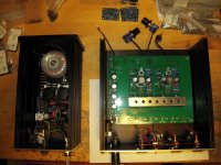
I used the spare 124 ohm resistor and wired it parrelel to the right channel as suggested. The R15 now measures 4.6 volts . And the R4 in the gives 0.37 volts so with 62 ohm it's 6 mA. And magic happens it works . If I were to go head and change the resistors to make it 10mA , what benefits do I get over the already seemingly working amp?
Attachments

It's alive!
10mA will get you an ACP+ that meets design specifications. The distortion numbers are probably higher with the lower current that you have right now. It still probably sounds good though.🙂
10mA will get you an ACP+ that meets design specifications. The distortion numbers are probably higher with the lower current that you have right now. It still probably sounds good though.🙂
Thanks for all the help, it's for sure alive!! I will definitely play ard with resistor and try to achieve 10mA !! More importantly I've learnt sth new about resistance and currents . Appreciate it guys
to lavil #1252
Hello lavil,
each JFet has a 'current range' in which it works / sounds best.
This is the reason why we match JFets and adjust the CCS so that
our JFets 'feel good'... 😀
Greets
Dirk
Hello lavil,
each JFet has a 'current range' in which it works / sounds best.
This is the reason why we match JFets and adjust the CCS so that
our JFets 'feel good'... 😀
Greets
Dirk
Lawil - As Ben says, 10mA will put the circuit at it’s optimal operating point. I’d expect it to sound better running as Nelson designed it. 
Okay what's everyone using for a case for the ACP+? I am going to start gathering the rest of the bits needed soon so I can build mine but haven't found a suitable case yet. Any suggestions on AliExpress etc?

- Home
- Amplifiers
- Pass Labs
- Amp Camp Pre+Headphone Amp - ACP+