Audiobear, this is far fetched but the positive lead of the right channel C2 looks quite long. Are you testing the ACP+ in a metal chassis and possibly the positive lead of C2 is shorting to ground? Or some other lead is shorting to ground? Or a bad C2?
Just trying to think of ways for the current to drain away causing the low power supply voltage.
Just trying to think of ways for the current to drain away causing the low power supply voltage.
I wish you were right! I am placing the board on spacers above the ground plane board and the pieces that stick out the bottom don't touch the board below. I will report some measured voltages tomorrow. The voltage across all but one of the resistors I tried to measure oscillates very quickly so there is no one reading. I get ranges like -0.5V to +3.5V. Both channels seem to have similar voltage ranges but it's hard to tell at the speed the numbers are changing on my DVM.
as it happens, I mounted the Q4 4N35s in sockets. Since Q4 is one of the suspects, I exchanged the two Q4 chips for one another to see if the working channel would follow the chip. To my surprise audio started up in both channels became very noisy and distorted and then the same channel dropped out. Although it was encouraging to hear both channels playing it seemed clear that Q4 is not the only problem. I am going to remove the sockets and solder the chips directly to the board to eliminate the chance bad contact is causing the problem. If I had any 4N35s in stock I would use new chips. This should at least eliminate Q4 as a potential cause of the problem.
My level of electronic knowledge is very limited. That said, it's hard to understand how the power is being dissipated without taxing the power supply and blowing a fuse. One would think a short would draw more power and produce heat. Intuitively, is seems more like the charging and discharging of a capacitor or a transistor ramping up and then switching off. The heatsinks never get warm either. There's nothing to say that there aren't multiple problems.
I'm going to take a very close look at C2, C3, and C4 next. Maybe even pull them out and test them. Q5 is next on the list. Looking forward to suggestions....
The ACP+ does not have a fuse to blow. I don't know a lot about switching power supplies but they might possibly shut down when their current capacity is exceeded. Perhaps that is happening.
C2 is in series with the V+ feed and R8. If C2 is bad, it could dump current to ground. It is worth checking C2.
I wouldn't think the sockets are a problem. You can check the solder joints to the board. You can also check continuity with a probe on the chip pins and the other probe at the pads on the bottom of the pc board.
The amp working for a short period is a good sign. But something is drawing down the voltage and stops it from working.
Here's where we are today:
1. I was in error in yesterday's post, the RiGHT channel produces no audio; the LEFT channel sounds fine.
2. Lifting R8 on both channels, as suggested by @amandarae, showed the Power input 24V filter is fine. When I reconnect the Left R8 that channel works fine and has rock solid voltages. Reconnecting R8 Right reintroduces the oscillation problem.
3. To answer @Ben Mah 's questions, yes the sound cycles with the power and the LED is synchronized with the power oscillation as expected.
[note: with R8 right in place voltages fluctuate]
4. The voltage across R4 left with R8 right lifted is 388mV (37.5 ohm/10.3mA) and the right with R8 in place are ±380-395mV (37.5 ohm/10.3mA)
5. Voltage across R15L is 4.74V and R15R is 3.95-4.12V
6. Voltage across R12L is 0.323V and R12R is 20-45mV. !!!!
7. DC1-->GND left = 10.87V and right =0.2-7.0V.
Right channel Q5 G is essentially 0V. I'm chasing that down now.
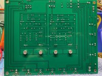
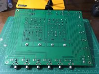
I would welcome suggestions and measured voltages to check. Thanks. The boards are getting scratched up and parts bent from all the handling. I may have to put this one in a case. Photos attached.
Hi may this helps, but it sure gives some work,
Unplug the board from all connections.
First, I would not SOLDER THE CHIPS to the board, it's rather seldom that SOCKETS are the Source of problem.
TAKE DVM and switch to OHM.
Check the channel which is working across the HIGH OHM RESISTORS and then check the same RESISTOR on the SIDE which is not working, Since both sides are same, the MEASUREMENTS MUST BE SAME.
Measure from high to LOW, with this I mean the Resistors..
Why? It has happen in the past months to me more than one time that these HIGH OHM " Resistors" were not accurate with what is printed on. More,it also has happen that 100K resistors where up in MB range.
And since it were all Vichai CMF 55 Series, and I see CMF 55 Series in that board, so this would be my first task. And it's only that you compare them from left to right or from good channel to none working channel.. no need to unsolder, just make sure that you use these +- Probes always the same way.
Meaning + in the left hand and tipping on the left side of the resistor and - on the right hand and measuring the right side, compare what you read, if there is one which is faulty, what I expect, then in 10 minutes you will find that one.
If that don't help check capacitors..
Not last but not least (but I doubt that this is the problem that ALPS VOLUME CONTROL)
Then last you would need to check that transistors from the failing side, the chips, no need to check because you have had sound..
If that doesn't help, check the tracks for HAIR CRACKS.
Hope that helps.
Last edited:
C6,7,8,9 appear to be 3300 uf not the specified 1000 uf. Little switching supply could be struggling to fill them. Are the other big caps the correct values? Camera angle seems to make them look wrong, not equal from side to side.
@hpro: thanks. I pulled and checked C2,C3, and C4 last night. They measured perfectly and there was no sign of a short. After I test it this morning I may take your advice. I like the below the line comment on your posts. I'm hoping to learn from this.
The very first ACP+ boards built by DIYers (on Bonus Day during Burning Amp Festival 2019), had no on-off switch at all. The wires from the wall wart were soldered directly to the PCB, so the unit was Always On unless the wart was unplugged from the mains.
Maybe there was a hidden good reason for this choice.
Maybe there was a hidden good reason for this choice.
C6,7,8,9 appear to be 3300 uf not the specified 1000 uf. Little switching supply could be struggling to fill them. Are the other big caps the correct values? Camera angle seems to make them look wrong, not equal from side to side.
@Fusor. Good eyes! They are actually 1 x 1000 and 3 x 3300s. I ran out of 1000s and have more on order. There's an illusion in the photo; the furthest one is actually a shorter 1000. I should have mentioned this on my original post. People are always putting larger caps in power supplies so I figured I could get by with the 3300s. With R8R lifted they seem to work fine for the working left channel but maybe your are right. I have some Nichicon "non-audio" 1000s that I could substitute.
Strange how the mind works, I completely ignored this parts value switch even though the symptoms kept suggesting a problem with a capacitor(s). I'm not sure this is the problem, or the only problem, since the two channels behave differently. We'll see sometime today or tomorrow. Thanks.
Try lifting the left channel R8, keep the right channel R8 in place and see if the right channel works.
Good catch by Fusor. Too much capacitance may be causing the SMPS to misbehave.
Also is the right channel C2 1000uF?
Good catch by Fusor. Too much capacitance may be causing the SMPS to misbehave.
Also is the right channel C2 1000uF?
@Fusor You were right! As confirmed by @Ben Mah. I went to the PO this morning and picked up a package from Digikey containing the Nichicon 1000 uF "audio" electrolytics. Earlier I had removed, tested and reinserted C2, C3, and C4. That improved the quality of sound in the working channel but did not eliminate the oscillation. Maybe a bad solder joint for one of those? We'll never know. When I replaced the 3000uF capacitors with the 1000uF electrolytics both channels came to life. Audio out of the headphone jack sounds very good--of course anything would sound good after this experience.
Lesson learned: when you don't know what you're doing ask someone who does. Or is it "a little knowledge is a dangerous thing?" I actually thought the extra capacitance in a filter circuit would make no difference at all.
Thanks to all of you we have the ACP+ working. Special kudos to Fusor's sharp eyes.
As I mentioned when I posted my oscillating ACP+, I built a second ACP+. The second ACP+ has a more conventional problem. The left channel plays well enough but the right channel is silent. This one has all BOM parts--no substitutions of capacitors this time! The position and value of each part has been verified and I have reflowed almost every joint. This makes for a messy board but doesn't solve the basic problem of a dead channel. Photos attached.
Some measured values are:
across R4 Left 747mV (10mA/68 ohms). R4 Right =0mV
across R12 Left 333mA. R12 Right 0
across R15 Left 4.73V R15 Right 0
across R8. Left 6.22V. R8 Right 0
across R6 Left 20.48V R6 Right 10.77V
across R7 Left 0.170V R7 Right 5.73
DCI--> GND Left 20.48 Right = 0
Gate Q6-->GND 4.75 Right = 0
My best guess is an open Q, but which one and how to test without removing semiconductors from the circuit? Or am I missing something even more obvious?
Attachments
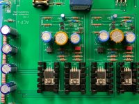
This is a different board from post 1278, correct?
When I look at the attached image, the R4 on the right side has color bands
blue, grey, black, gold (maybe reflection, it actually look silver from my old laptop), violet.
This color bands is 68R.
Looking at the left side of the image, the color band is
violet, black, black, black, violet
If this is the case, this R4 is 700R which will be way way too high, 7R or 70R will be more likely.
Can you confirm the value?
@pchw: Yes it is a different board and I think I'm going to cry. The one thing I didn't check was the two resistors that I was switching in and out of R4 to get 10mA. They should be the same 68 ohm resistors since I was swapping them in pairs. @pchw, you have sharp eyes. I don't think the resistor is a 700R because I don't have any of those but it should have been a 68R. I wish I had looked as carefully as you did at the photo I posted. I am not at home until tomorrow morning but will verify then that you have found a major problem--hopefully the only problem. I sort of know you're right because when I cleaned up my bench this afternoon before heading out I found a single 68R resistor sitting on the desktop. Instead of realizing where it belonged, I just put it back in the store of 68R resistors without giving it a second thought. I had lots of other things on my mind. Another lesson learned today. I'll post the outcome tomorrow.
@pchw I have an afterthought; if the resistor is brown black black black brown which it kind of looks like to me, it's 100R. That's more likely since I have 100R blue Yageo resistors. That brings the question if a 100R would produce the problems I am seeing. Since the original R4 value was 125R I kind of doubt it. We'll find out tomorrow afternoon.
All's Well That Ends Well with second ACP+
@pchw: The R4 right resistor was in fact 100R.
With the schematic and DVM in hand, I went point to point measuring voltages until I decided Q3 was the problem. I replaced Q3 with a J113 that nearly matched J113 Left. The voltage across R4 now measured about 560mV instead of 0. Switching in a 47R for the 68R resulted in 10.9mA across R4 right which fortuitously turns out to be the same current observed across R4 left. Both channels now play and all sounds good. I guess I must have fried the J113 when soldering it or else shorted it out somehow. Whatever fried Q3, all's well that ends well. Thanks to those of you that helped along the way in this adventure. It was a good learning experience.
Congratulation!!
Last night, I curve traced all 100 J113's that were just delivered by UPS last evening.
None of them is a perfect 10 (mA) for R4 = 125R, but all of them would turn on with a 100R, i.e would produce some voltage across R4. Since you had a 100R and no voltage reading, I suspected you had a open Q3; however, I was too tired to post afterward. FWIW, a J310 can also be used as Q3, too.
I am glad that you have solved it. It is always a good feeling to solve a mystery 🙂
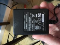
Whoops wrong adapter...
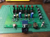
Hi All, I've been following along at home and got everything installed (and learned a decent amount about jfets in the process). Reached the point of plugging it in and testing voltages when I realized I had the wrong size power socket for the Triad adapter. Went fishing through my rack gear and other adapters and found a 24v that fit...plugged it in and...a few seconds later a burning smell and some smoke! LED glowing solid. Unplugged and with great embarrassment realized the adapter was 24VAC. Went the next day and got an equivalent adapter with correct barrel size, plugged that in and it seemed to be charging the caps and blinking the LED as NP describes, did that for a minute or two and then gave up. LED dimmed and gave out.
So, best guesses, what have I fried? I've already desoldered and replaced R18 and R19 (one of which had a nice searing underneath, as you can see), as well as C6 and 7. I've been following the voltage down the line and get 24v up to R20 but I was hoping for some guidance as to how to debug this and get it working...or if I've completely shot it...😕
Thanks all in advance!
Hi All, I've been following along at home and got everything installed (and learned a decent amount about jfets in the process). Reached the point of plugging it in and testing voltages when I realized I had the wrong size power socket for the Triad adapter. Went fishing through my rack gear and other adapters and found a 24v that fit...plugged it in and...a few seconds later a burning smell and some smoke! LED glowing solid. Unplugged and with great embarrassment realized the adapter was 24VAC.
Went the next day and got an equivalent adapter with correct barrel size, plugged that in and it seemed to be charging the caps and blinking the LED as NP describes, did that for a minute or two and then gave up. LED dimmed and gave out.So, best guesses, what have I fried? I've already desoldered and replaced R18 and R19 (one of which had a nice searing underneath, as you can see), as well as C6 and 7. I've been following the voltage down the line and get 24v up to R20 but I was hoping for some guidance as to how to debug this and get it working...or if I've completely shot it...😕
Thanks all in advance!
Attachments
Audiobear, that is great news.
jonnyampersand, that is terrible. At this point check the following voltages:
1. DC1 to Ground, should be around 11V
2. across R12, should be about 0.33V
3. across R4, depends on value of R4, but should not measure 0V
4. across R15, should be about 4.5V
jonnyampersand, that is terrible. At this point check the following voltages:
1. DC1 to Ground, should be around 11V
2. across R12, should be about 0.33V
3. across R4, depends on value of R4, but should not measure 0V
4. across R15, should be about 4.5V
Some voltages seem to be oscillating?
DC1 (this is the same as V+ ?): 0-13.5V
Both R4s: 0.52V across 100R
R R15: 0-4V
L R15: 0-3.9V
R R12: 0.03V
L R12: 0.13V
Also below is the new adapter:
Maybe relatedly, I was assuming the switch near the LED was either to switch input or output, but is actually on/off?
DC1 (this is the same as V+ ?): 0-13.5V
Both R4s: 0.52V across 100R
R R15: 0-4V
L R15: 0-3.9V
R R12: 0.03V
L R12: 0.13V
Also below is the new adapter:
Maybe relatedly, I was assuming the switch near the LED was either to switch input or output, but is actually on/off?
Attachments
- Home
- Amplifiers
- Pass Labs
- Amp Camp Pre+Headphone Amp - ACP+