It's all in the original article:
"The preamp circuit has a gain of 9 dB flat from about 5 Hz to just under 200 KHz (-3 dB)"
So Av is about x3.
You do the maths from here.
"The preamp circuit has a gain of 9 dB flat from about 5 Hz to just under 200 KHz (-3 dB)"
So Av is about x3.
You do the maths from here.
Just wondering what the gain of the circuit is when acting as a preamp?
Second year EE students are subjected to a certain misery called Thevenin Equivalent Circuits, which they always hate, and which they always whine "What is the PRACTICAL USE of this ridiculous nonsense?"
And now we have an answer, here in the real world! Thevenin Equivalent Circuits allow you to calculate the gain of the ACP+ when acting as a preamp. Just what we want, oh boy!
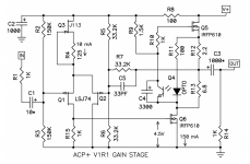
In the schematic below, replace (V+ and R5 and R6 and Ground) by its Thevenin Equivalent Circuit. Yes really.
Then connect this equivalent circuit to R7, and channel your inner Emeril Lagasse: BAM! The gain falls into your lap.
Now email your old professor and apologize for doubting his teaching.
_
Attachments
Second year EE students are subjected to a certain misery called Thevenin Equivalent Circuits, which they always hate, and which they always whine "What is the PRACTICAL USE of this ridiculous nonsense?"
Oh boy, there's a blast from the past. Between Thevenin and Norton, I had a few sleepless nights.
Beginner's Luck Runs Out
I restarted DIY electronics after a 50 year hiatus--no joke, 50 years since I built Heathkits, Dynacos and the rest. I have forgotten what little electronics I ever learned but am slowly relearning. So far I have been very lucky with everything I've built. It all just worked.
I thought building ACP+ boards would be easy. It's a beautiful board. Lots of space and great layout. What could go wrong? So I started two boards at the same time that I have been slowly assembling. One will go in a case and the other will sit naked on the ground plane.
Today I attempted to check them out and adjust the current across R4 before completing assembly. Both boards will need some troubleshooting help but before we get to that I need to ask a question about a parts substitution.
After reading the sticky "Replacement For Toshiba 2SK170/2SJ74" I directly substituted 2SJ74s for the LSK74s with no modifications. Is this retro-substitution ok? Seems like it should be. I got the 2SJ74s from a friend who got them from Punkydawgs so I know they're ok. They measured just about identically on the Atlas DCA Pro.
Was using these my first mistake?
Awesome - thanksIt's all in the original article:
"The preamp circuit has a gain of 9 dB flat from about 5 Hz to just under 200 KHz (-3 dB)"
So Av is about x3.
You do the maths from here.
https://www.mouser.com/datasheet/2/408/6903-18063.pdf
2SJ is Toshiba. LSK is Linear Systems (diyaudiostore). It should be fine! Data sheets below.
https://www.mouser.com/datasheet/2/408/6903-18063.pdf
https://www.linearsystems.com/lsdata/datasheets/201175%20-%20LSJ74%20Rev%20A6%20dated%202017%2010%2006.pdf
After reading the sticky "Replacement For Toshiba 2SK170/2SJ74" I directly substituted 2SJ74s for the LSK74s with no modifications. Is this retro-substitution ok? Seems like it should be. I got the 2SJ74s from a friend who got them from Punkydawgs so I know they're ok. They measured just about identically on the Atlas DCA Pro.
Was using these my first mistake?
2SJ is Toshiba. LSK is Linear Systems (diyaudiostore). It should be fine! Data sheets below.
https://www.mouser.com/datasheet/2/408/6903-18063.pdf
https://www.linearsystems.com/lsdata/datasheets/201175%20-%20LSJ74%20Rev%20A6%20dated%202017%2010%2006.pdf
Last edited:
Okay what's everyone using for a case for the ACP+? I am going to start gathering the rest of the bits needed soon so I can build mine but haven't found a suitable case yet. Any suggestions on AliExpress etc?
foam board 🙂
viral projects, sort of
Need troubleshooting advice on ACP+ (First Board)
As I prepared to build the ACP+ I read NPs original article and this forum thread several times and made copious notes. I made a special point of trying to collect the troubleshooting posts. Unfortunately, I have a problem that hasn't been posted here or in any other forum I have read. I find it sort of humorous. I have built what I guess you could call it a low frequency oscillator. The blue led flashes on and off with a cycle of 1.6 sec. See the YouTube at Blinking Blue LED - YouTube
First off, no components get hot and there is no smoke. The circuit seems stable. It has operated for several hours to no ill effect. I see no solder bridges or joints that look cold; I've reflowed a few. I have verified several times that I have all the right parts in all the right places.
I have tried 3 different 24V wall warts and all produce the same result. The voltage at the 24V PS input plug builds up-to about 12V and discharges to around 6. It does not go to 24V as expected. Somewhat amazingly, to me at least, I was able to pick 37.5 ohm resistors for matched J113s that resulted in 10.3mA across both right and left R4s. I plugged in Audeze LCD-1 headphones and both channels were playing, albeit with some noise. Volume is equal in both channels and the volume control works as expected. It seems like both pre-amp channels are functional.
This leads me to believe that the problem lies in the portion of the circuitry common to both channels. That doesn't leave much to choose from beyond the RC network at the input or the input plug itself. I really don't know enough to do anything but mindlessly remove/replace components one by one. My question is what conclusions can I draw from these observations and what should I do to isolate the problem?
I will post pictures after we discuss what the evidence should be telling me. I'd like to learn a little bit more about the problem solving process first. I will say that coping with an oscillation common to both channels has been a stumper to me, but I'm expecting (hoping?) that the source of the problem will be obvious to many of you.
I suggest measuring the voltage drop across R18, R19, and R20 to determine current at each location. Perhaps a bad capacitor? Bad solder joint?
Is the voltage at the PS plug cycling between 12V and 6V in time with the LED?
Is the sound also cycling?
What are the voltages at the two audio channels: across R4, R15, R12, at DC1 to Ground? Are they also fluctuating?
Is the voltage at the PS plug cycling between 12V and 6V in time with the LED?
Is the sound also cycling?
What are the voltages at the two audio channels: across R4, R15, R12, at DC1 to Ground? Are they also fluctuating?
Silly Q but can I swap the J113 for a J112 if I can get 10mA through R4?
Q3 serves as a CCS so if you can get 10mA with a J112, then should be no problem.
Thanks to all of you above for the questions and suggestions. If I can get back to the project sometime this afternoon I will try to provide some answers and pictures.
Q3 serves as a CCS so if you can get 10mA with a J112, then should be no problem.
Thank you for confirming my thoughts.
Are your power supplies high enough current?
Two are the Triad in the BOM and the other is 24V Meanwell 5A24V supply used for the ACA. These should be fine.
I suggest measuring the voltage drop across R18, R19, and R20 to determine current at each location. Perhaps a bad capacitor? Bad solder joint?
Is the voltage at the PS plug cycling between 12V and 6V in time with the LED?
Is the sound also cycling?
What are the voltages at the two audio channels: across R4, R15, R12, at DC1 to Ground? Are they also fluctuating?
Here's where we are today:
1. I was in error in yesterday's post, the RiGHT channel produces no audio; the LEFT channel sounds fine.
2. Lifting R8 on both channels, as suggested by @amandarae, showed the Power input 24V filter is fine. When I reconnect the Left R8 that channel works fine and has rock solid voltages. Reconnecting R8 Right reintroduces the oscillation problem.
3. To answer @Ben Mah 's questions, yes the sound cycles with the power and the LED is synchronized with the power oscillation as expected.
[note: with R8 right in place voltages fluctuate]
4. The voltage across R4 left with R8 right lifted is 388mV (37.5 ohm/10.3mA) and the right with R8 in place are ±380-395mV (37.5 ohm/10.3mA)
5. Voltage across R15L is 4.74V and R15R is 3.95-4.12V
6. Voltage across R12L is 0.323V and R12R is 20-45mV. !!!!
7. DC1-->GND left = 10.87V and right =0.2-7.0V.
Right channel Q5 G is essentially 0V. I'm chasing that down now.
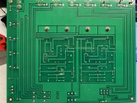
I would welcome suggestions and measured voltages to check. Thanks. The boards are getting scratched up and parts bent from all the handling. I may have to put this one in a case. Photos attached.
Attachments

The voltage is fluctuating because there is a unusually high current drain somewhere. Since there is very little current flowing through R12R, the current through R4 is normal, and when R8 is removed, the voltage goes back to normal, the excess current may be flowing through R5 or R9. So measure the voltage drop across those to try to track down the current flow. While you are at it, also measure the voltage drop across R6, R7, and R13. More information is better.
Perhaps Q4 or Q6 is bad.
Q5 G at 0V may point to bad Q4.
Perhaps Q4 or Q6 is bad.
Q5 G at 0V may point to bad Q4.
Last edited:
Don't have this board, but look at the right side of the back image, the middle pin of Q2 doesn't look soldered solidly. If this i the right channel, perhaps it is worth to reflow it.
Anyhow, if you get 45mV, i.e. 0.045V from R12, which is 2R2, that means Q5 is passing approx 20mA which is way too low. Can you measure the voltage across R5 and R9?
Anyhow, if you get 45mV, i.e. 0.045V from R12, which is 2R2, that means Q5 is passing approx 20mA which is way too low. Can you measure the voltage across R5 and R9?
- Home
- Amplifiers
- Pass Labs
- Amp Camp Pre+Headphone Amp - ACP+