to Dangermouse #1180
Hello Dangermouse,
I use the ACP+ with my Beyer DT880Pro (250 Ohm - version).
Outputresistance can be adjusted to the demands of different headphones.
I don't remember the number of the post in this thread, where the formula /
resistance table is described. I think it was Ben Mah? not sure....
My Beyer likes the ACP+. Sounds really good. I also built the Whammy and Waynes Line Stage (to drive headphones). All three preamps are great - as preamp and as headphoneamps. Each has its special 'character'.
Greets
Dirk
Hi Dangermouse,
I am using my ACP+ as a headphone amp on Audio Technica ATH M50 (38 ohms),AKG K240 (55 ohms), AKG 702 (62 ohms), and Senn HD 650 (300 ohms). All good. I don't hear/sense any shortcomings. Enjoy. Godspeed.
I am using my ACP+ as a headphone amp on Audio Technica ATH M50 (38 ohms),AKG K240 (55 ohms), AKG 702 (62 ohms), and Senn HD 650 (300 ohms). All good. I don't hear/sense any shortcomings. Enjoy. Godspeed.
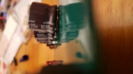
I managed to make the caps I had work. Not only did I accidentally order caps with 7.5mm lead spacing, the caps for C2,6-9 were 15mm wide. So that I didn't have to bend the leads so much to get them to fit, I stuck an o-ring under them to act as a spacer. The o-rings also helped the caps stand up straight as well.
Quick question, about the use of insulators under the C5,6 mosfets. Is they for electrical insulation, or are they more for aiding with heat transfer?
Quick question, about the use of insulators under the C5,6 mosfets. Is they for electrical insulation, or are they more for aiding with heat transfer?
Attachments

Shared PSU with ACA?
Since I still need to come up with an enclosure for my ACA, I'm thinking about building a single enclosure to house my ACP+ as well. Is there anything I need to consider if I am to run everything off of a single power supply?
I'm not sure how well it will work out, but this is the power supply I'm planning to use for now. It should have plenty of capacity, but I just don't know about noise. It's an industrial power supply, but it does seem like a rather high quality unit so my fingers are crossed.
Instead of waiting to see if there is any noise in the audio, there anything I can do ahead of time to evaluate the power quality from this unit?
Last edited:
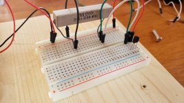
So I'm new to all of this, and I was reading that it wouldn't hurt to match the Q3 jfets. I figured that since I have a couple extra, I'd at least try to use the two with closest values.
I'm using the same process described on how the diyaudio store makes their matched sets, but I'm not sure how to interpret my results. I'm using a new 9v battery, but the voltage drop across the 100 ohm resistor steadily drops once I apply power. Is this normal, or is there something wrong with my testing process?
I'm using the same process described on how the diyaudio store makes their matched sets, but I'm not sure how to interpret my results. I'm using a new 9v battery, but the voltage drop across the 100 ohm resistor steadily drops once I apply power. Is this normal, or is there something wrong with my testing process?
no dead horse, but - considering how long ago I used those boards, I even forgot how they''re arranged
anyway, before anyone else chime in, it'll be useful if you post sch of your test setup, so we can be on same page
anyway, before anyone else chime in, it'll be useful if you post sch of your test setup, so we can be on same page
When I'm measuring across the resistor, I'm getting between 10.88v and 10.81v.
I'm probably just showing my ignorance, which I don't have a problem with because I'm trying to learn. But it seems to me I should have the resistor between the signal and ground instead, otherwise why not measure the voltage drop between the drain and signal+ground pins?
I'm probably just showing my ignorance, which I don't have a problem with because I'm trying to learn. But it seems to me I should have the resistor between the signal and ground instead, otherwise why not measure the voltage drop between the drain and signal+ground pins?
Attachments
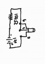
measure voltage across resistor, divide with 100R, that is Ids
you're getting at least 10 times of what is expected - either your JFets are Dodo, or you did not connected something by schmtc, which is good for N JFets
for P JFets just opposite polarity of battery
btw. it is irrelevant where you put resistor , bellow JFet or above
you're getting at least 10 times of what is expected - either your JFets are Dodo, or you did not connected something by schmtc, which is good for N JFets
for P JFets just opposite polarity of battery
btw. it is irrelevant where you put resistor , bellow JFet or above
When I'm measuring across the resistor, I'm getting between 10.88v and 10.81v.
I'm probably just showing my ignorance, which I don't have a problem with because I'm trying to learn. But it seems to me I should have the resistor between the signal and ground instead, otherwise why not measure the voltage drop between the drain and signal+ground pins?
I use fig9 in this page, all explained there
Biasing JFETS
resistor values, positions, mosfet positions?
Start at the beginning. Have you verified that your DC power source is indeed providing +24vdc ? I also noticed that you've wired all of your I/O off the board so it is hard to see how you wired the switch or the DC power inlet.
--Tom
I'm thinking Q2 in my right channel is bad. I have just shy of 20v to ground at DC1, and 13.26v to ground at the Q2 gate.
- Home
- Amplifiers
- Pass Labs
- Amp Camp Pre+Headphone Amp - ACP+