Thanks for your help!
I've finished this build and it half works, the left channel tests and works as expected, but the right channel measures ~19V at DC1 and doesn't audio. I've inspected it for misplaced components and don't see anything obvious. I am curious if this could be the R4 issue and how I'd go about determining this and what value of resistor I might use.
......
As for my right channel problems, I performed some of the measurements suggested and found 0 volts across R13. It's been a few decades since electronics lab, but I'm going to work on measuring everything on both channels and trying to find a place where things diverge.
Having voltage at DC1 and no voltage across R13 point to Q6 (IRF610) not conducting current. That could be due to bad solder joint, bad Mosfet, or not enough voltage at the gate of Q6. The voltage at the gate of Q6 can be measured across R15 (see schematic which shows 4.5V across R15 and at gate of Q6).
So if you do measure 4.5V or so at R15, it is likely Q6 is defective, or bad solder joint.
If you do not measure 4.5V, then most likely there is something not right with the subcircuit with the JFETs Q1, Q2, and Q3. Measure the voltage across R4 in addition to the voltage across R15.
The voltage across R4 and R15 will be used to determine whether there is current flowing through the JFETs.
Measure the good channel also. The voltage across R4 will also be used to determine whether R4 needs adjustment.
Thanks for the guidance. I performed the following measurements:
Right (non functional)
R15 2.4V
R4 0.4V
Left (functional)
R15 4.8V
R4 0.9V
In addition I resoldered everything in the vicinity of these, and replaced Q3 as I have extras, however there was no change.
I assume R4 is 125R right now. The left channel has quite low current through the JFETs. Either R4 needs to be lower in resistance or Q1, the LSJ74, is not functioning properly. I am assuming since you replaced Q3 and the results did not change, then Q3 is not the problem. For now you should investigate R4, as R4 in conjunction with Q3 controls the current. Change R4 to something around 50 to 60 Ohms and measure again.
The ideal current through Q3 and R4 is 10mA. Use Ohm's Law to calculate the current through R4.
Ohm's Law: V = I*R, so I = V/R
Currently for the right channel, I = 0.4V/125R = 0.0032A = 3.2mA (pun intended)🙂
Hopefully with a lower value R4, the current will increase. The new current needs to be calculated using the measured voltage across R4 and the value of R4.
If the issue is with R4, the current should increase with the new R4. If it doesn't, then that points to something wrong with Q1, the LSJ74.
Help please- Blown right channel
Had only run preamp for a few hours after build and it sounded great!
I got up off couch and reached for volume, there was a static discharge to volume and right channel died.
I checked DC1
Left 10.58 v
Right 1.6 v
R13 L 1.089v, R 1.331v
R4 L 1.349, R 1.331
R15 L 4.63, R5.41
R14 L3.2mv,R0.3mv
After searching about channel issues posts I changed Q6 on right channel but still ng
Blow right channel
Mine did the exact same thing. I changed the pot, opto and 610’s on the Right channel and that didn’t fix it. I then ordered a new matching quad if JFETS, and that fixed it. Makes me nervous now each time I touch the volume pot.
Mine did the exact same thing. I changed the pot, opto and 610’s on the Right channel and that didn’t fix it. I then ordered a new matching quad if JFETS, and that fixed it. Makes me nervous now each time I touch the volume pot.
Right channel blown
Thank you for the troubleshooting info! I just ordered another set of matched jfets from diy store. I am very much a newbie but, I was wondering if there is a way to run some sort of ground to reduce the chance of this happening again,
Thank you for the troubleshooting info! I just ordered another set of matched jfets from diy store. I am very much a newbie but, I was wondering if there is a way to run some sort of ground to reduce the chance of this happening again,
I assume R4 is 125R right now. The left channel has quite low current through the JFETs. Either R4 needs to be lower in resistance or Q1, the LSJ74, is not functioning properly. I am assuming since you replaced Q3 and the results did not change, then Q3 is not the problem. For now you should investigate R4, as R4 in conjunction with Q3 controls the current. Change R4 to something around 50 to 60 Ohms and measure again.
The ideal current through Q3 and R4 is 10mA. Use Ohm's Law to calculate the current through R4.
Ohm's Law: V = I*R, so I = V/R
Currently for the right channel, I = 0.4V/125R = 0.0032A = 3.2mA (pun intended)🙂
Hopefully with a lower value R4, the current will increase. The new current needs to be calculated using the measured voltage across R4 and the value of R4.
If the issue is with R4, the current should increase with the new R4. If it doesn't, then that points to something wrong with Q1, the LSJ74.
I jumped a 48 ohm resistor in on R4 for an effective resistance of about 34 in hopes of getting about 10mA across it and found that the voltage on DC1 became 12V. Based on this I changed out R4 for the 48 ohm resistor (my next lowest is 22 ohm) and it measured about 12V again, so I hooked it up and I have functioning audio in both channels. I now measure 236mV across R4, so it's only passing about 5mA. I don't know if I should be concerned by this, or perform any further measurements, troubleshooting, adjustments, or just enjoy the sound.
Thanks everyone for their help, and especially Ben Mah.
That's great news.
The ACP+ is functional so you can enjoy the sound.
However with only 5mA going through Q3, most of it is taken up by Q1, so Q2 is not functioning as it should, as normally 5mA goes to Q1 and 5mA goes to Q2. So you end up with a bit more distortion.
You can adjust R4 until 10mA is attained. Perhaps something around 36R?
Do both channels since your other channel is low also.
By the way, the other channel's J113's R4 will be different so you will need to determine the correct value independently.
Last edited:
Need help, no voltage at DC1
Hi,
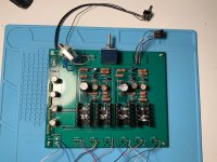
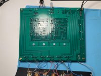
Completed the build and turned on the power, measured no voltage at DC1, not Mr. Pass mentioned 11v, and the voltage drop across R18 is 0.05v, not Mr. Pass mentioned 0.3v. The LED did turn on. Could anyone help? I use a DPDT toggle switch I already have for panel mount and just connect 3 terminals on one side and left the other 3 on the side unconnected.
Hi,
Completed the build and turned on the power, measured no voltage at DC1, not Mr. Pass mentioned 11v, and the voltage drop across R18 is 0.05v, not Mr. Pass mentioned 0.3v. The LED did turn on. Could anyone help? I use a DPDT toggle switch I already have for panel mount and just connect 3 terminals on one side and left the other 3 on the side unconnected.
Attachments
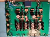
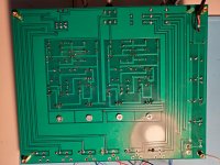
Resistor and capacitor values, jfet and mosfet followed what Mr. Pass specified. I changed the phone jacks and rca jacks to panel mount, and used a panel mount dpdt switch I had instead of the ones specified.
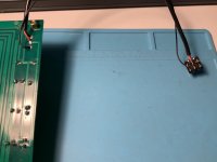
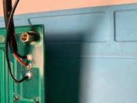
I suspect how I wired the switch was incorrect. By the way, I did reflow every soldering points but the issue remained.
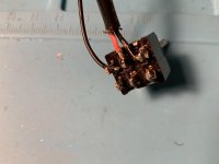
Here are the pictures of the power switch connection, I connected it with a dpdt toggle switch from the back side.
Attachments
- Home
- Amplifiers
- Pass Labs
- Amp Camp Pre+Headphone Amp - ACP+