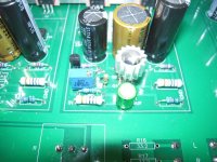
Nice! Great sleuthing Ben Mah!! Shouldn’t R4 be a pot in this circuit instead of a fixed resistor first time around? Here is what Papa says in the original document: “ In the case of R4, the J113 Jfets I had in stock had a higher Vp, so the value is adjusted from 68 ohms up to 125 ohms to give the 10 mA current source value.”
Best,
Anand.
Best,
Anand.
Last edited:
Thank you everyone. Shall I further try lower R4?
Post #1160
Or adjust it until you get about 10mA (as per schematic suggest). Congrats!
If you optimize the circuit for 10mA, then it will be to specification and the distortion profile will be as intended.
Enjoy!
Enjoy!
R4 ma range
Thanks for the feedback! I was wondering if being slightly over was a bad thing in this case.
Thanks for the feedback! I was wondering if being slightly over was a bad thing in this case.
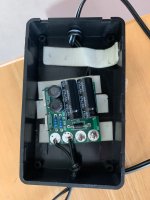
My brother gifted me a P089ZB filter (block box). I can say that I really like it and to me, there's an improvement in the performance of the ACP+ with the filter in line with the power source.
The filter is designed by Mark Johnson and the thread is here PO89ZB , an inline DC filter for SMPS wall warts . Preamps, HPA, Korg NuTube, etc
The filter is designed by Mark Johnson and the thread is here PO89ZB , an inline DC filter for SMPS wall warts . Preamps, HPA, Korg NuTube, etc
Attachments
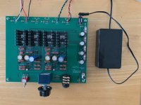
You may not realize it yet, but your brother used the really good electrolytic capacitors discussed in that thread, and your filter is 3X better than the first one I built in May 2020.
You may not realize it yet, but your brother used the really good electrolytic capacitors discussed in that thread, and your filter is 3X better than the first one I built in May 2020.
Thank you Mark! Nice to know. I am reading the thread and I saw the caps mentioned there (3x lower in ESR in Post# 214).
Nice! Great sleuthing Ben Mah!! Shouldn’t R4 be a pot in this circuit instead of a fixed resistor first time around? Here is what Papa says in the original document: “ In the case of R4, the J113 Jfets I had in stock had a higher Vp, so the value is adjusted from 68 ohms up to 125 ohms to give the 10 mA current source value.”
Best,
Anand.
I was thinking about this after I had the same struggles that seem to come up with R4 for some. Then I realized that a pot is probably a poor solution at best, as we're adjusting a resistor to control current, not voltage. You wouldn't know the resistance you've set to calculate the current.
that's trivial - series fixed resistor of fixed value
10R is enough, and say 200R trimpot
10mA through 10R is 100mV, good enough for precision
and all that, if someone doesn't want to observe half of set current across R15
10R is enough, and say 200R trimpot
10mA through 10R is 100mV, good enough for precision
and all that, if someone doesn't want to observe half of set current across R15
to JamesHH #1174
Hello JamesHH,
yes, a potentiometer can make it easier. After you have adjusted the pot to
get the correct current out of the ccs (J113 and R4) you can desolder the pot
and insert a resistor with the same value like your pot is adjusted. Easy.
Greets
Dirk
Hello JamesHH,
yes, a potentiometer can make it easier. After you have adjusted the pot to
get the correct current out of the ccs (J113 and R4) you can desolder the pot
and insert a resistor with the same value like your pot is adjusted. Easy.
Greets
Dirk
Attachments
I'm fine with trimpot staying in
not exactly Shinkoh type of DIYer
Cermet is good enough for my old ears
not exactly Shinkoh type of DIYer
Cermet is good enough for my old ears
This has happened a few times now. Diyers have built the ACP+ using the official schematic and BOM and then have run into problems. It seems that the current production J113 needs the R4 to be much lower than 125R.
It is best to have the official schematic and BOM revised to reflect that. Or at least a note added to the DiyAudio Store ACP+ page advising purchasers that the R4 value is not exact, and may need to be lower than 125 Ohm, and point to this thread for information.
It is best to have the official schematic and BOM revised to reflect that. Or at least a note added to the DiyAudio Store ACP+ page advising purchasers that the R4 value is not exact, and may need to be lower than 125 Ohm, and point to this thread for information.
Agree with Ben Mah and and Zen Mod, and maybe diystore can also sell the board with critical parts such as R4 and J113 combo that can get close to desired current 10ma, as an option for those first time diyers like myself. Maybe that's too much work for diystore to arrange such option. Luckily we got people here kind and patient enough to walk me through trouble shooting. Thank you. 
I currently have 7mA or so through R4 and it sounds very good already, but don't have lower value resistor to get close to 10mA. I will order some lower value resistors and hopefully fine tune further.
I currently have 7mA or so through R4 and it sounds very good already, but don't have lower value resistor to get close to 10mA. I will order some lower value resistors and hopefully fine tune further.
Last edited:
Hello my friends,
I have some 2sj74 left an this could be a good way to use them.
But i only own an old 600 Ohm Beyerdynamic DT990 & and a new HD650 300 Ohm.
I`ve build an Whammy which drives both very well.
What can i expect from ACP+ ?
Especially with this Cans far away from optimized 32 Ohms?
Do anyone have both Headphones in use with this Headamp?
excerpt from Article:
Of particular note, the gain circuit has been optimized around a 32 ohm load, and performs
best at this impedance. Not that it can't drive other loads, as you will see, but it will retain the
same qualities driving 32 ohm headphones as it does the RCA output with that load.
- Home
- Amplifiers
- Pass Labs
- Amp Camp Pre+Headphone Amp - ACP+