re what I tried:
- red RCA to red on ACA and white to white
right speaker to ACA’s B output an left speaker to A = ... no sound from right speaker
- swap RCAs... still no sound from right speaker
- red RCA to red on ACA and white to white
right speaker to ACA’s A output and left speaker to B... no sound from left speaker
- swap RCAs... still no sound from left speaker
- red RCA to red on ACA and white to white
right speaker to ACA’s B output an left speaker to A = ... no sound from right speaker
- swap RCAs... still no sound from right speaker
- red RCA to red on ACA and white to white
right speaker to ACA’s A output and left speaker to B... no sound from left speaker
- swap RCAs... still no sound from left speaker
Can you hear the normal speaker thump as you turn the amp on and off?
If you can then you have continuity to the speaker and the fault is probably elsewhere... such as input wiring.
Are all the DC conditions correct? midpoint approx at 12 volts and the FET's getting normally hot?
If you can not hear the thump from the bad channel then carefully trace the wiring from each of the speaker terminals back to the PCB using a low ohms range on the meter.
managed to set DC midpoint at about 12.01/5 on both boards
no power on thump but definitely a power off one
no power on thump but definitely a power off one
ok, so...
outputs (speaker terminals) are both at about 970-980 Ohm
inputs (RCAs) are...
49.9 kOhm on B input (red) and...
weird, fluctuating readings on A input (white) :-/
outputs (speaker terminals) are both at about 970-980 Ohm
inputs (RCAs) are...
49.9 kOhm on B input (red) and...
weird, fluctuating readings on A input (white) :-/
If the channel with no audio gives a power off thump then the connectivity to the speaker has to be assumed to be good. So it appears you have an input problem.
Connect an RCA lead to the bad channel input (because we are going to measure from the other open end of the RCA lead itself) and confirm that the outer ground part of the loose plug has 0.00 ohms connectivity to the ground terminal of the PCB. This should also mean you measure 0.00 ohms between this point on the RCA lead and the positive speaker terminal.
Now measure from the centre pin of the RCA plug to the centre terminal of the RCA socket. It should be zero ohms.
Leaving one lead of the meter still on the centre pin of the loose plug continue working back from the socket to the board. You should continuity all the way back to the PCB input terminal.
Connect an RCA lead to the bad channel input (because we are going to measure from the other open end of the RCA lead itself) and confirm that the outer ground part of the loose plug has 0.00 ohms connectivity to the ground terminal of the PCB. This should also mean you measure 0.00 ohms between this point on the RCA lead and the positive speaker terminal
0.18 Ohm all of those (both channels)
Now measure from the centre pin of the RCA plug to the centre terminal of the RCA socket. It should be zero ohms
0.16 Ohm (both channels)
Leaving one lead of the meter still on the centre pin of the loose plug continue working back from the socket to the board. You should continuity all the way back to the PCB input terminal
Huston we have a problem: "white" RCA has continuity between center and ground
happens between input + and ground on PCB too
(this is also the input I couldn't measure input resistance of, see my post above)
weird as... right speaker ("red" RCA) was the one with no sound :-/
thinking about it... this is the second ACA I built and I rushed out all final connections to end it before the evening
might have shorted input + and g, on that channel, to the chassis? (not enough wire in these 1.6 kits to solder everything while keeping parts... well apart 🙄 )
Last edited:
It sounds like you have a simple error somewhere. You will have to just go over it all very carefully.
You could begin by unsoldering the audio input lead on the PCB and seeing if your short is either on the board or in the wiring. With the input lead unsoldered at the PCB there should be infinite resistance between RCA centre and ground.
It sounds an easy fault to correct, you just have to be methodical.
Make sure any wiring around the switch is OK.
before unsoldering anything I'm waiting for Amazon to deliver some "L" shaped screwdrivers so I'll first remove "the metal thing" (no idea how it's called in english 😛 ) that holds together the heatsink and chassis' front/back panels so I can inspect underneath the PCB first 😉
delivery is scheduled in a few hours at max
delivery is scheduled in a few hours at max
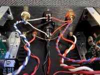
got those screwdrivers and... everything's fine underneath the PCB: nothing's shorting on the heatsink, there 🙂
input wires soldering on the PCB are fine too
but... think I got where the issue (... hopefully) is: see the blob on white RCA's center pin? hard to tell (and this phone can't focus this close) but looks it's shorting there behind 🙄
removing some solder in a while and re-checking afterwards 😉
input wires soldering on the PCB are fine too
but... think I got where the issue (... hopefully) is: see the blob on white RCA's center pin? hard to tell (and this phone can't focus this close) but looks it's shorting there behind 🙄
removing some solder in a while and re-checking afterwards 😉
Attachments
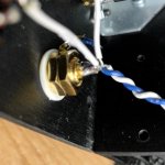
... most uncomfortable spot to get to with a soldering iron and solder sucker :-/
anyway... excess solder removed, no continuity anymore between center pin and "outer shell" and... measuring 49.9kOhm input resistance
re-assembling it all and proceeding with... sound test 😉
anyway... excess solder removed, no continuity anymore between center pin and "outer shell" and... measuring 49.9kOhm input resistance
re-assembling it all and proceeding with... sound test 😉
yes: solder blob definitely was the culprit 🙄
both ACAs working fine and sounding great, now
thank you @Mooly (and you all) so much indeed 🙂
both ACAs working fine and sounding great, now
thank you @Mooly (and you all) so much indeed 🙂
yes: solder blob definitely was the culprit 🙄
both ACAs working fine and sounding great, now
thank you @Mooly (and you all) so much indeed 🙂
I had to pay a professional a few hundred NZD to work out why my valve amp stopped working when all I'd done was re-cap it and replace the ageing speaker terminals at the rear. I had to widen the holes in the case just a bit and the drill created a tiny burr that I didn't see that earthed one terminal to the case. Stopped the whole thing working.
While the pro was working trying to find the problem I bought an ACA as I needed a low watt amp for high sensitivity speakers. Then a bit later I bought a second one and packed the valve amp away in it's box.
I love the ACA's in my setup.
yes: solder blob definitely was the culprit
thank you @Mooly (and you all) so much indeed 🙂
Yes, well done. And it was simple to fix...
bridged monos working (finally) and sounding great 🙂
btw... this configuration sounds louder than the SIT 3 😱
(volume knob at 9+ instead of 11 for same SPL)
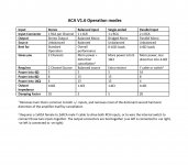
can someone, please, recap here differences (in output power) among:
stereo
balanced monos
bridged monos
parallel monos
thanks 🙂
btw... this configuration sounds louder than the SIT 3 😱
(volume knob at 9+ instead of 11 for same SPL)
can someone, please, recap here differences (in output power) among:
stereo
balanced monos
bridged monos
parallel monos
thanks 🙂

thank you 🙂
weird: 15w vs SIT 3's 18 but... sounding louder (everything else being the same)
might be just bad memory (not swapping back to the FW for a while 😉 )
Last edited:
The gain of the SIT3 is pretty low (about 12dB?) If I'm not misunderstanding things,
the single-ended input bridged mono ACA has about 20dB gain. That would
explain why at the same volume setting of the preamp, the ACA is louder.
the single-ended input bridged mono ACA has about 20dB gain. That would
explain why at the same volume setting of the preamp, the ACA is louder.
- Home
- The diyAudio Store
- Amp Camp Amp Kit 1.6/1.8