Hi, those red leds are alternatives for the blue ones.. You may use whichever color you want to your liking 👈
If you choose LEDs that do not come with they kit version, pay careful attention to the voltage rating as you may have to insert a resistor or blow out the LED.
My suggestion is to try both parallel and bridged and balanced if you have a balanced preamp, (or even back to the single chassis stereo) and see which you prefer. That’s the advantage of the switching in V1.8 you can quickly change a speaker cable or 2 and flip the switch and so can compare the options. Speakers are a complex load, so one can’t say for sure
in conclusion, with new switch , may i know the position for stereo, bridge and parallel?
down : stereo & balance
center : off for both (???)
up : bridge rca
is this right? sorry for stupid question.
down : stereo & balance
center : off for both (???)
up : bridge rca
is this right? sorry for stupid question.
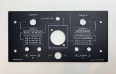
If you have wired the 3 position switch as the v1.8 diagram,
Switch UP = Bridged Mono. Using the White RCA input and output from the Black speaker sockets.
Switch Centre = Normal Stereo mode using the 2 RCA inputs, or Balanced Bridged Mono using the XLR input.
Switch Down = Parallel Mono mode. (Remember link the Black speaker connections together too.) In this mode you can use either RCA input and either pair of Red and Black output sockets.
Attachments

Another suggestion that I often do simply to not make simple mistakes after a long build session. When in doubt, convince yourself of the switch positions by determining which ones are enabled at which position by getting out your DVM on Ohm mode and testing across the leads of the switch.
Standoffish
Hi All, first post and I wondered if I could be pointed in the right direction please?
I am on step 15 on the ACA1.8 build and one of the brass standoff's has not been machined very well and won't thread. The other is fine and fits in both heat sinks so I'm sure it's the stew that is at fault. I don't really want to force it and cross-thread the heatsink so is this a part that is easy to get hold of? I am in the UK so would need to get this from Italy if not...
Any thoughts/advice/help greatly appreciated.
David
Ordered a couple of these so fingers crossed:
https://uk.farnell.com/wurth-elektronik/971050324/standoff-hex-male-female-11mm/dp/2988152
https://uk.farnell.com/wurth-elektronik/971050324/standoff-hex-male-female-11mm/dp/2988152
Hi David,
They are M3 standoffs and yes easy to get in the UK. (M3 or 3mm Metric thread)
Measure the ones you have for length, the threaded part and hexagonal part just to be sure. I suspect they are 6mm thread and 5mm hexagon.
Then ebay is the cheapest and quickest option. This is just an example: Hex M3 Male Pillar Standoff Hexagonal Brass Spacer Support | eBay
It is not necessary to have brass, nylon is just as good. White Nylon Male M3 Thread Pillars + Nut Plastic PCB Spacer Studs Hex Standoff | eBay
Alan
David,
Those will be fine as long as the heatsink hole is not 'blind', otherwise you may have to shorten the threaded section a few millimetres.
Those will be fine as long as the heatsink hole is not 'blind', otherwise you may have to shorten the threaded section a few millimetres.
Sorry you got a bad part David. The threaded holes are "blind". One first step would be to try and screw it into a M3 nut and see if you can get it to "catch" At least there's no risk as there would be screwing it into the heatsink.
If that doesn't work and your replacement has a too long threaded part, screw on the M3 nut before cutting it shorter so that after filing or cutting it, you can unscrew the nut to clean up the thread damage from the cutting.
In some cases even the standoffs we supply DON'T screw all the way into the heatsinks but are about 1mm away from the hex part contacting the sink. This is actually perfectly fine, they don't have to screw all the way in to work perfectly. Please keep us informed as to how things work out..
Last edited:
Hi Jason, where can I get a correct, current parts list which includes part ID, type and values for Build 1.8
The one shown in Build 1.6 Step 1 is now incorrect because R13 is different and missing items eg: P1
In Step 6 there's an instruction sheet visible, where could that be found.
Appreciate your assistance, Mark.
The one shown in Build 1.6 Step 1 is now incorrect because R13 is different and missing items eg: P1
In Step 6 there's an instruction sheet visible, where could that be found.
Appreciate your assistance, Mark.
The parts for 1.8 are identical to 1.6, the changes are all on the back panel.
Resistors are 1/4w unless noted on the schematic as 3W
Capacitors are 25V or greater, though C2 will never have more than a few volts across it and the kit supplies a 16V in that position.
R13 does nothing more than set the brightness of the LEDs. More ohms=dimmer.
P1 has always been a part of this amp.
The "instruction sheet" you see in that photo was the sheet included in the box with the 1.6 kit. There is a similar sheet in the 1.8 kit.
Last edited:
No problem, these things happen. Good tip about the M3 bolt, that may have cleared it, but the replacement standoff worked just fine. Everything is now on the heatsinks waiting to be wired up. Thanks for all of the prompt responses, it is very much appreciated and a testament to the community you have here, I may well be back if it doesn't work...🙂
Sorry you got a bad part David. The threaded holes are "blind". One first step would be to try and screw it into a M3 nut and see if you can get it to "catch" At least there's no risk as there would be screwing it into the heatsink.
If that doesn't work and your replacement has a too long threaded part, screw on the M3 nut before cutting it shorter so that after filing or cutting it, you can unscrew the nut to clean up the thread damage from the cutting.
In some cases even the standoffs we supply DON'T screw all the way into the heatsinks but are about 1mm away from the hex part contacting the sink. This is actually perfectly fine, they don't have to screw all the way in to work perfectly. Please keep us informed as to how things work out..
opened today, and started building, a v1.6 kit from May 2018 batch
(bought two, back then. built one, was working fine and I gifted it to a friend)
in this second kit though... 0.47Ohm resistors are completely missing 😱
could someone, please, post specs/Mouser part # for those?
and whilst at it... those for the new three-way back switch too?
pity just a few days ago I ordered from Mouser components for a σ11 LPS and, this round, I'll be charged 20€ shipping for just these few parts 🙁
thank you all
Last edited:
There is nothing special about the specific resistors. 0.47ohm 3W metal film. Anything you could get locally or from a distributor in Italy will work perfectly.
The new switch is a DPDT on-off-on toggle switch.
The new switch is a DPDT on-off-on toggle switch.
Just finished my 1.8 kit build. The amp sounds wonderful! And there is absolutely no noise, hiss, hum or anything to distract from the music.
About the 12V setting: How close is close enough? It is nearly impossible to get it to exactly 12V. I assume a few 100ths of a volt either way is fine?
About the 12V setting: How close is close enough? It is nearly impossible to get it to exactly 12V. I assume a few 100ths of a volt either way is fine?
- Home
- The diyAudio Store
- Amp Camp Amp Kit 1.6/1.8