
What tolerance % for the resistors I should go for, 5% tolerance is widely available and cheaper than 1%.1/2 or 0.5 watt will be closest. In fact 1/4 watt, 0.6 watt even 1 watt will all be fine.
If I go for 5% tolerance, do I compromise with audio quality ?
well, not exactly that tolerance is a problem , but no one can guarantee that 5% ones aren't total waste of time and money
I mean , when 1% are so cheap, those are certainly old stock carbons and if they are, everything is possible to end with - horror ......... or good ones
you can use them, of course and most likely - if you get regular quality, hardly any difference to 1% ...... speaking of ACA, where signal level is highish and noise is not so critical ..... as is in phono preamp, for example
I am assuming you will choose metal film and not carbon resistors.
You can use 39k in place of 39.2k (R12 etc). 330k in place of 332k (R10) and 2.2k in place of 2.21k (R15).
You can use 39k in place of 39.2k (R12 etc). 330k in place of 332k (R10) and 2.2k in place of 2.21k (R15).
Sure, I will go for metal film and thanks for clarifying the R12, R10 and R15 doubts in advance! 🙂I am assuming you will choose metal film and not carbon resistors.
You can use 39k in place of 39.2k (R12 etc). 330k in place of 332k (R10) and 2.2k in place of 2.21k (R15).
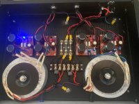
Hoping to get some help with an external PSU supply I built for my amp camps. 2 toroidal as-2220, 4 CapMX power supply boards, and 4 wire umbilical cords for each channel (2 wires are V+, both 0V grounds together, and the last is safety ground)
I noticed the right channel has a small hum that can be heard with ear 1 foot away and I would like to fix it.
I confirmed it’s for sure the right side power supply as I switched the amps, tried the setup in different locations, and tested with the left channel turned off.
The hum is only there when rcas are plugged in and I confirmed it’s there with cheater plug connected.
Wondering if I could add CL-60 between the 0V and chassis for each channel where the umbilical adapters are going out the PSU or maybe something in my wiring can be corrected.
Any help is appreciated.
Attachments

I am doing DIY for first time and thinking If I use 4700uf for C1 instead of 3300uf, would it make any sonic difference?
I will use Meanwell 24v smps as in ACA kit for power supply.
I will use Meanwell 24v smps as in ACA kit for power supply.
You may not hear a difference. Possibly more meaningful would be the choice of the capacitor. Electrolytic capacitors come in various grades, from general purpose to audio grade. Since the audio signal passes through C1, you may or may not hear a difference between a general purpose and an audio grade capacitor. There are many opinions but this is diy so you can try it for yourself.
Have a read at this from post #14. The thread wanders around.Hoping to get some help with an external PSU supply I built for my amp camps. 2 toroidal as-2220, 4 CapMX power supply boards, and 4 wire umbilical cords for each channel (2 wires are V+, both 0V grounds together, and the last is safety ground)
https://www.diyaudio.com/community/threads/3-stage-lin-topology-nfb-tappings.101321/post-1623053
Post #45:
https://www.diyaudio.com/community/threads/3-stage-lin-topology-nfb-tappings.101321/post-1626642
Dneu2011, I noticed that the AC live wires are twisted together and the AC neutral wires are twisted together. Instead each pair of live and neutral wires should be twisted together (left channel live and neutral twisted together and right channel live and neutral twisted together).
You mentioned that only the right channel hummed. I see that the AC lines cross the right channel DC lines. Try connecting the right channel PS DC to the amplifier left channel and the left channel PS DC to the amplifier right channel. Does the hum switch channels?
And yes, try the ground lift too.
You mentioned that only the right channel hummed. I see that the AC lines cross the right channel DC lines. Try connecting the right channel PS DC to the amplifier left channel and the left channel PS DC to the amplifier right channel. Does the hum switch channels?
And yes, try the ground lift too.
I couldn't find 1% tolerance so had to buy 5% ones.5% will not make any difference to audio quality...
If it bothers you buy a few more and 'match' them with your meter. You often cannot buy low numbers in the UK so you can select the closest values.
When I checked with multimeter, they have avg tolerance between 2-3% except
2.2k which is 5% so actual value 2.1k.
Please advise if it's fine or I have to look further which is difficult at my end or may have to import from USA or UK which will be very costlier.
If it's fine I will make sure to use best close match of available as I bought them in more quantity than required.
Thanks.
Thanks a lot. 🙂just go for it
tolerance is not an issue for ACA
Thanks for the advice! I’ll correct the twisted live and neutral wires.Dneu2011, I noticed that the AC live wires are twisted together and the AC neutral wires are twisted together. Instead each pair of live and neutral wires should be twisted together (left channel live and neutral twisted together and right channel live and neutral twisted together).
You mentioned that only the right channel hummed. I see that the AC lines cross the right channel DC lines. Try connecting the right channel PS DC to the amplifier left channel and the left channel PS DC to the amplifier right channel. Does the hum switch channels?
And yes, try the ground lift too.
quick update on what I did on the unit yesterday:
- added CL-60 to each grounding wire and connected to chassis.
- combined my safety grounds at the back of the PSU
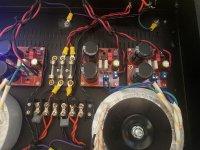
- I narrowed the problem down to the specific board. I removed the fuse for the working (left) side of the power supply to focus on the troubled right side. The 3rd one from the left is the problem board I identified. When it is attached it caused hum on both channels when only testing one amp, but when I remove it the hum goes away when I’m just testing a single channel on that amp.
I did some resistance comparisons on the boards and noticed a difference on R24 (100k ohm). When I checked it in circuit on the “bad” board it showed 100k, which is what that resistor is, but when tested on the good boards, I get around 50k ohm on that same resistor. I replaced the 3 KSC1845 transistors, the IRFP9140 Mosfet, and confirmed the R24 resistor is still good. I thought maybe the trimmer resistor was bad and replaced it, but I am still getting 100K across that resistor.
Can anyone see anything on this schematic that I might be missing? I am thinking something should be in parallel with R24 to get the value to 50k to match the other boards.
Thanks!
Attachments
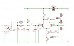
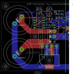
dunno for pcb, but schmtc is fishy ( and that's Eagle, so pcb must be result of it)
big mosfet D and S looks shorted
why 9140?
it's late/long day (at least in my brain), but isn't logical to have N channel mosfet there ?
edit: I don't like amplified cap-multipliers; whatever you do, you end up with sort of gain stage ....... and then you must make it faster than actual amplification you have as load
if any, simple passive cap multi-followers are no brainer, be it with fat mosfet or darlington ( for lower voltage drop)
I’ve been using these boards for awhile. I bought a bunch from Rudi and these are my last four. The 9140 N channel device is the one I always use for this PSU.
big mosfet D and S may be shorted… I test for continuity between D and ground and S and ground and getting 2.6M ohm… on the working boards I’m getting OL.
I did replace this mosfet with a new one, so something else could be wrong.
Any other parts to check?
big mosfet D and S may be shorted… I test for continuity between D and ground and S and ground and getting 2.6M ohm… on the working boards I’m getting OL.
I did replace this mosfet with a new one, so something else could be wrong.
Any other parts to check?
One more challenge I come across is the ZTX450 transistor availability. It is not available in most of the places, please suggest the alternative if possible.
Thanks.
Thanks.
- Home
- Amplifiers
- Pass Labs
- Amp Camp Amp - ACA