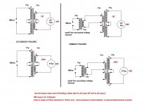
The 2 secondary 18 volt windings need to be added together, and guess the sequence of wires should be yellow - red to yellow - red. The red to yellow will be the centre tap, one yellow to either ~ connection, the free red to the other ~.
Sorry Zen Mod, double post...
Sorry Zen Mod, double post...
Last edited:
Mooly, interesting, just going by the Hammond rectifier chart, a bi phase rectifier gives 1 to 1 current availability, AC to DC (into a capacitor + load) where as a 4 diode bridge gives 0.6 current availability AC to DC.
You have to look at it in context. The two diode set up assumes the combined total voltage of the windings, so an 18-0-18 transformer is taken as a 36 volt winding (Vdc = 0.707 * Vac) and the single winding is taken as 18 volt (Vdc = 1.414 * vac). Same difference you might say.
Each single winding on its own might be rated at 1 amp for example. So I dc is taken as '1' of the secondary windings ability.
In the our specific example of using two separate 18 volt windings we have them in parallel and so we effectively have made a single 2 amp 18 volt winding. Now because we are using it more efficiently (pulling less current each 10ms from each winding instead of pulling lots of current every 20ms for the two diode version) we can say a current of I dc of '0.62' but that is now of what is effectively a 2 amp winding, not a 1 amp. So 0.62 of 2 is 1.24.
If we were comparing a single 18v 1 amp winding we would be worse off current wise but we have two windings in parallel now.
The higher the peak current (such as in a two diode set up) then the higher the copper losses in the transformer become and because it is I 2 R (where 2 means squared) then they become very significant.
Hope that reads all right 🙂
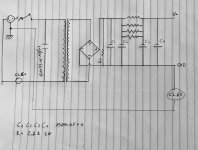
Hi, I found a toroidal transformer with only one secondary 20v 200va without center tap. Could I use it for ACA Amp?

This is the power supply I would like to make with the 200va 20v transformer I found for little money. I have to buy the capacitors, are 4 x 15000 uf capacitors enough for 2 channels? I have attached the schematic so you can tell me if it is correct or if there are better solutions.
Attachments
Which JFETs to be used for ACA amp as it has following options to choose from:
Thanks for the quick response. I will go with 8-11 mA.both are appropriate
you don't need quad
ideally just matched pair, goes one/ channel
I will buy 6-8 mA, thanks.You need about 4.5 to 4.7 volts across the 1k resistor R9, equivalent to 4.5 - 4.7mA, so the lower idss fet is fine.
Are Multicomp pro brand resistors of better quality ?
In India, only 0.47 ohm 3w resistor available from Vishay and 0.68 ohm 3w from Multicomp pro.
Is it fine to use different brand resistors for R1 and R3?
In India, only 0.47 ohm 3w resistor available from Vishay and 0.68 ohm 3w from Multicomp pro.
Is it fine to use different brand resistors for R1 and R3?
Use what is available. The Panasonic power have either been discontinued or soon to be discontinued.
Multicomp pro is the "house brand" of Newark (and its associated companies). I have not had problem with their parts, though you should check the specs to see if you like what you see. 🙂
Multicomp pro is the "house brand" of Newark (and its associated companies). I have not had problem with their parts, though you should check the specs to see if you like what you see. 🙂
Thanks for sharing your experience about Multicomp pro.Use what is available. The Panasonic power have either been discontinued or soon to be discontinued.
Multicomp pro is the "house brand" of Newark (and its associated companies). I have not had problem with their parts, though you should check the specs to see if you like what you see. 🙂
Both R1 and R3 resistors are available with Multicomp pro.
Shall I go for same brand for both or it is fine to mix Vishay and Multicomp for R1 and R3 ?
- Home
- Amplifiers
- Pass Labs
- Amp Camp Amp - ACA