I am using a 160va 2x 0-18v for Aca Amp. If I use V+ and Gnd, I use all 8 Caps or only half of them?
I built one like this out of spare parts I had on a bread board. But set up both sides of the PSU to be exactly the same at +24V where each side has its own separate CRC with 40,000uf.Hi, two years ago I built the ACA Camp amplifier. Now I would like to build the Aleph J amplifier. In the meantime I am waiting for Aleph J's pcb to be available, I have built the psu. This psu has V+ V- and Gnd. The ACA Camp only has V+ and Gnd. I am wondering if I can use this psu for ACA Camp and if so how to do it.
Thank you
i used an 18 volt secondary 200va Antek transformer but the voltage drop was a bit more than expected and had 23V rails. Still sounded VERY nice. I would use a 20 volt secondary transformer if I built one again the same way.
Attachments

do you want to temporary use already made dual rail psu for single rail ACA?I am using a 160va 2x 0-18v for Aca Amp. If I use V+ and Gnd, I use all 8 Caps or only half of them?
or you want to change it for permanent use with ACA, using everything to full potential?
I would like to make one specifically for ACA but I don't know how to do it, or I can modify this to use it to its full potential, but only if I can then restore it to the original; and then, when the material is ready, use this for Aleph j.
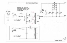
thank you Dneu2011, I would like to build a psu like this. Please, could you give me a schematic for this psu? Or is there a pcb on ebay?I built one like this out of spare parts I had on a bread board. But set up both sides of the PSU to be exactly the same at +24V where each side has its own separate CRC with 40,000uf.
i used an 18 volt secondary 200va Antek transformer but the voltage drop was a bit more than expected and had 23V rails. Still sounded VERY nice. I would use a 20 volt secondary transformer if I built one again the same way.
I thought the Aleph J needed at least a 300VA transformer?
Build another supply just for the ACA and use your 160VA transformer there. Just build the Positive (top half) of the supply you cannot use the negative half so why use it? Then parallel connect the 18 volt secondaries. Or follow Dneu2011 and build 2 positive supplies and power each ACA channel individually.
Build another supply just for the ACA and use your 160VA transformer there. Just build the Positive (top half) of the supply you cannot use the negative half so why use it? Then parallel connect the 18 volt secondaries. Or follow Dneu2011 and build 2 positive supplies and power each ACA channel individually.
Attachments
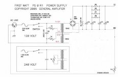
Thank you Alan, this transformer is only for ACA. The PSU board I bought on diyaudio store is for the Aleph J and / or F6. At the moment, however, they are not available and so I wanted to temporarily use this board for ACA just to see if there is any sonic difference respect the original power supply. If i see that the sound improves, then i will build a psu with the scheme you sent me.I thought the Aleph J needed at least a 300VA transformer?
Build another supply just for the ACA and use your 160VA transformer there. Just build the Positive (top half) of the supply you cannot use the negative half so why use it? Then parallel connect the 18 volt secondaries. Or follow Dneu2011 and build 2 positive supplies and power each ACA channel individually.
I still have a question, I have a transformer that has 230-0v in the primary and not 115-0 0-115. I would like to know if I can use the thermistor with this transformer, and if it is possible how put it?

Sorry if this is the wrong place to ask, but I can’t figure it out: when can we expect the Mini ACA in the diyaudio store? Thanks!
I connected V + and Gnd but I think that I am using half transformer in this way, in fact with the amplifier on I get 20v instead of 24. Without load I am 24.5v. it's like using an 80va transformer instead of a 160va. Can I connect the two secondaries together in order to use the whole transformer?use positive rail and GND, ignore/do not use negative rail
if you want to use it permanently and use full potential of Donut and caps, confirm
Thank you, can I use the diode bridge or do I have to buy two single 35A 200v diodes?That is the 'best' solution. It also slightly increases the amount of current available.
Use the diode bridge.
Connect the 2 x 18 volt transformer wires to the AC ~ terminals and use the +ve as the output. Leave the -ve disconnected, it has no function.
The -ve / 0 volt line is now the centre tap (where you joined the 2 x 18 volt secondaries together.
Connect the 2 x 18 volt transformer wires to the AC ~ terminals and use the +ve as the output. Leave the -ve disconnected, it has no function.
The -ve / 0 volt line is now the centre tap (where you joined the 2 x 18 volt secondaries together.
Last edited:
Sorry I do not understand the question.
If you already have the 35A 200 volt Bridge rectifier(s) use one of those. If not then buy one and use it as described.
If you already have the 35A 200 volt Bridge rectifier(s) use one of those. If not then buy one and use it as described.
Sorry, I write the message before to read your answer. Now I have delete the messageSorry I do not understand the question.
If you already have the 35A 200 volt Bridge rectifier(s) use one of those. If not then buy one and use it as described.
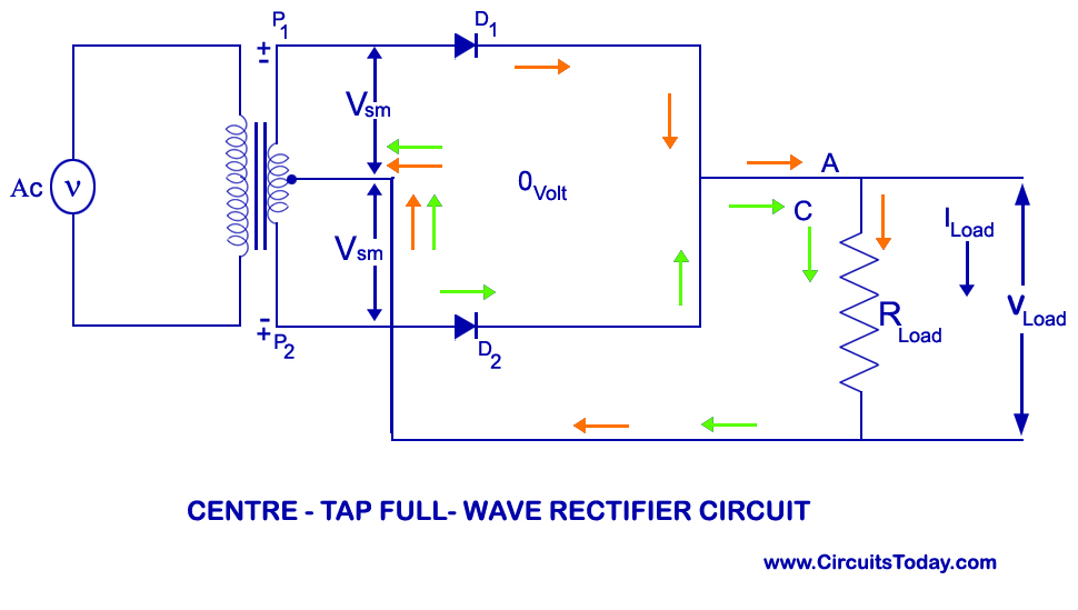
Would the peak transformer secondary current be halved using the two windings in parallel and a four diode full wave bridge vs the two diode full wave version?
On a 'per winding' basis the four diode bridge draws secondary current every 10 milliseconds (50Hz mains) while the two diode would draw twice the current per winding but now only every 20 milliseconds.
The two diode version gains a fraction in output voltage because there are fewer diode losses in the circuit but the transformer has a much easier time of it with a four diode bridge. Don't under estimate the peak transformer currents when the load current is high (such as an ACA). They could easily be in the 15 amp region for a two diode version, half that for a four diode bridge.
Edit... added 'but the transformer has a much easier time of it with a four diode bridge'
I connected the psu as indicated, using only half psu. Everything is fine without the load, but when I turn the amplifier on, there is a loud hum from the psu board or from the transformer and I have to turn it off immediately.
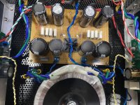
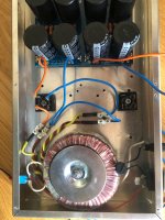
I am attaching a photo to show if I have connected right. The red cables of the transformer are 0V
I am attaching a photo to show if I have connected right. The red cables of the transformer are 0V
Attachments
- Home
- Amplifiers
- Pass Labs
- Amp Camp Amp - ACA