@ahaiden
Eliminate any problem with your source and speakers first. Swop the speakers round and then the inputs. Does the imbalance stay the same side of the ACA?
If the problem is with the ACA, next measure the resistance between the speaker terminals. Red to Black should be about 500 to1000Ω on your 2kΩ range.
Then measure the resistance between the RCA outer ring and central socket. With your meter on 200kΩ you should measure about 50kΩ each side.
General questions - Using one channel at a time, does one channel sound distorted if you turn up the volume? Which channel is louder? Please say Red or White (as the RCA washers).
Do the 4 large transistors (on the heatsink) all get equally hot after 10 minutes?
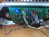
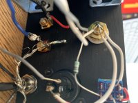
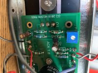
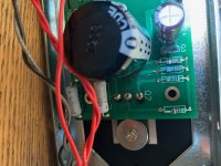
Please post some better pictures, of the back panel from the wiring side and flat on of each ACA board.
Alan
Eliminate any problem with your source and speakers first. Swop the speakers round and then the inputs. Does the imbalance stay the same side of the ACA?
If the problem is with the ACA, next measure the resistance between the speaker terminals. Red to Black should be about 500 to1000Ω on your 2kΩ range.
Then measure the resistance between the RCA outer ring and central socket. With your meter on 200kΩ you should measure about 50kΩ each side.
General questions - Using one channel at a time, does one channel sound distorted if you turn up the volume? Which channel is louder? Please say Red or White (as the RCA washers).
Do the 4 large transistors (on the heatsink) all get equally hot after 10 minutes?
Please post some better pictures, of the back panel from the wiring side and flat on of each ACA board.
Alan
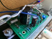
Sorry about the previous lack of pictures, it's been a bit of a nightmare to get them to upload. So the resistance of the speaker terminals being fed by the red RCA channel is 350 ohms red to black, and for the terminals being fed by white RCA the resistance is 980 ohms. For the RCA's themselves measuring center to outer, the resistance is 50k ohms for both the red and the white.
I did try flipping RCA inputs, that didn't change anything (I tested using a mono track), and regarding individually turning up the volume, there isn't any distortion. The white channel is the louder channel. Regarding transistor temperatures. It was a little bit difficult to tell, but they all seemed equally hot.
Thanks again for the help, I really appreciate it!
Attachments
-
 84D933B8-C9F9-43AC-9D84-C2BEB34C387B.jpg947.2 KB · Views: 338
 -
 5500F15B-3580-444A-87FF-0EE81B72A09F.jpg725.6 KB · Views: 323
 -
 35B5344F-E35C-4970-BAC5-2D5B5F42D41E.jpg977.3 KB · Views: 323
 -
 E4D4BB0D-C62F-4F3F-AF5F-34C4326149B1.jpg992.2 KB · Views: 305
 -
 0E2B4D15-B843-4C94-A75E-F78654FB7A8C.jpg986.1 KB · Views: 326
 -
 F3486357-05A9-4B48-8A5B-7CF7274B3E3D.jpg959.2 KB · Views: 144
The 350Ω reading on the Red channel is wrong.
If your meter reads nearly 1kΩ on the White channel you should have the same result from the Red. Please try it again and give it 60 seconds or so for the meter to give the highest reading. (I should have mentioned the rear switch needs to be in the centre position for these tests.)
If you still get the low reading there is something wrong round the R11, R12 and R14 areas.
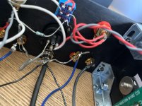
Have a very careful look down the back of the Red channel board and make sure there are no leads touching the chassis or bridging tracks on the board.
Check they are the correct values and measure them with your meter.
Sorry to mention, but there are a few 'problems in waiting' with several of the wires to the rear panel, either loose strands or poor solder connections. They might not be the immediate issue, but they will be future faults.
If your meter reads nearly 1kΩ on the White channel you should have the same result from the Red. Please try it again and give it 60 seconds or so for the meter to give the highest reading. (I should have mentioned the rear switch needs to be in the centre position for these tests.)
If you still get the low reading there is something wrong round the R11, R12 and R14 areas.
Have a very careful look down the back of the Red channel board and make sure there are no leads touching the chassis or bridging tracks on the board.
Check they are the correct values and measure them with your meter.
Sorry to mention, but there are a few 'problems in waiting' with several of the wires to the rear panel, either loose strands or poor solder connections. They might not be the immediate issue, but they will be future faults.
"Sorry to mention, but there are a few 'problems in waiting' with several of the wires to the rear panel, either loose strands or poor solder connections. They might not be the immediate issue, but they will be future faults."
+1 You said it much nicer then I was going to.
Also, wasn't it mentioned that it "sparked" upon one of the turn-ons? If so, I would assume it took out a resistor or two?
+1 You said it much nicer then I was going to.
Also, wasn't it mentioned that it "sparked" upon one of the turn-ons? If so, I would assume it took out a resistor or two?
I did the check again and they come out almost identical this time. I'm not sure what I did differently last time, as I waited till it reached steady state and the switch has been in the center the whole time (as far as I am aware).
I agree that the wiring at the rear panel is not great, I've never soldered before and I found doing the wiring as opposed to the PCB was much more difficult.
Regarding the sparking, the power center and power ring were connected by my poor soldering the first time, which I would expect meant that when that happened, the current never reached the resistors, correct?
Well I realized that I had neglected to do one of your checks, Alan, which was to switch the cable wires. And sure enough, the issue didn't switch with the wires like they should have, so I thought it might be a speaker issue, so leaving the wires in place at the amp, I switched the speakers, but the issue didn't switch with the speakers. I have a REL subwoofer that inputs from the amplifier level, so in order to eliminate variables, I removed its connection and now the problem is gone. So now it's time to figure out what's going on there.
Thanks for the patience and help!
Thanks for the patience and help!
I read your last post as, '' the ACA works fine without the REL Sub connected'' ?
First guess is that there is an earth / ground connection problem with the ACA and REL used together.
Just remember the ACA is unusual in that the RED speaker terminals are the Ground / 0volt connections. It might help you understand the problem.
Sorry I've no experience with RELs, but others may have ideas or suggestions.
Alan
Help needed.
I have recently noticed that when I switch my ACA mono amps on(bridged mono ver.1.8) that my speakers pulse about four times.
The speakers are Markaudio Alpair 12P in pensil cabinets.
I also have ACA ver.1.6 stereo amp that does not cause speakers pulse when switched on.
The rest of my system is Audiolab 6000CDT,Geiseler Kompakt R2R DAC and Korg B1 pre.
Thank you in advance for help received.
Hard to say for sure without seeing/hearing it but first thought would be to look at the power supply and make sure the 24 volts is stable from the moment of power on.
Are you using the recommended Meanwell PSU?
You could also try connecting a speaker (via a suitable cap) to each amp output in turn and seeing if one or both are doing this. You may need to short the inputs of both to get a valid result on that. The ACA does make strange noises on power on and power off but these can cancel somewhat in bridge mode.
Hard to say for sure without seeing/hearing it but first thought would be to look at the power supply and make sure the 24 volts is stable from the moment of power on.
Are you using the recommended Meanwell PSU?
You could also try connecting a speaker (via a suitable cap) to each amp output in turn and seeing if one or both are doing this. You may need to short the inputs of both to get a valid result on that. The ACA does make strange noises on power on and power off but these can cancel somewhat in bridge mode.
I bought the full kits from the Diyaudio store.
The amps are switched to bridged mode before I power them on.
Both amps do same thing
I do not switch on the fly.
What sized cap would you recommend.
Thank you Mooly for the reply.
I bought the full kits from the Diyaudio store.
The amps are switched to bridged mode before I power them on.
Both amps do same thing
I do not switch on the fly.
What sized cap would you recommend.
Thank you Mooly for the reply.
470uF or larger and 25v working or higher. It was just to see what noise each amp channel makes on its own.
We do know the ACA makes noises but four pulses from each speaker sounds a bit different.
if you are annoyed at the speakers having issues at turn on, better to use a speaker time delay relays....they are so dirt cheap nowadays....12V DC Delay Relay Delay Turn on / Delay Turn Off Switch Module with Timer | Lazada PH
the ACA is a single ended and asymmetrical, there will be issues at turn on, it take seconds for the operating points to stabilize to design values...1/2 of b+ is all there is to look out for at the output node at the +side of the output coupling cap...
the output coupling caps ensured that your speakers are safe....there will be annoyances, you can minimize them, and that is all you can do...
Last edited:
- Home
- Amplifiers
- Pass Labs
- Amp Camp Amp - ACA