I have a very basic question: is it possible to connect a single ended preamp to a pair of ACA running as monoblocks? How is the ground/neutral connection in the XLR on the ACA made to the preamp?
Also, as I asked earlier in this thread, is there are 24V (external?) linear power supply designed for use with the ACA?
Also, as I asked earlier in this thread, is there are 24V (external?) linear power supply designed for use with the ACA?
Yes. Use the RCA input and the bridge switch.
If you want to go through the bother, expense, and poorer performance of powering these with a linear power supply, it’s on you to design and implement it.
Instead, to take the performance up instead of down, consider a post-SMPS filter… look into rthatcher ‘s CLC filter, or Mark Johnson’s.
If you want to go through the bother, expense, and poorer performance of powering these with a linear power supply, it’s on you to design and implement it.
Instead, to take the performance up instead of down, consider a post-SMPS filter… look into rthatcher ‘s CLC filter, or Mark Johnson’s.
Thanks - I didn't realize that there is a bridging switch. I thought this happened when you used the XLR input.
I am a bit surprised to hear that a linear power supply would be less good than the supplied switching power supply. I think that most of Nelson Pass's amps have linear power supplies, right?
I am not qualified to design a power supply; that I am sure of.
I am a bit surprised to hear that a linear power supply would be less good than the supplied switching power supply. I think that most of Nelson Pass's amps have linear power supplies, right?
I am not qualified to design a power supply; that I am sure of.
Ground Wire making a circuit to the frame rails
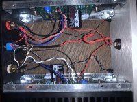
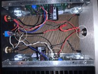
So I got done assembling the amp and it double checked everything and it all looked good. So I tried plugging it in and the power brick started beeping. So I thought maybe the brick was faulty but I noticed it was in the parallel mono mode, so I switched to stereo mode and tried again. This time I noticed some sparks when I plugged it in, so I quickly unplugged everything and called it a night.
Today when I came back to it I started doing continuity checks to see what might be going on, assuming I had let a wire + solder make contact with a heat sink. So I stuck one end of the multimeter on the rail and then used the probe to start interrogating components.
I soon found that everything connected to the ground wire was causing the probe to go off. So I took of the rails to be able to inspect but nothing is making contact from the PCB to the heatsink. Plus I can’t get a continuity check to work through the heatsink, the front panel or the back panel. But I can get the continuity check to beep from each individual rail to the rail that I clipped the multimeter to. I’ve looked everywhere for stray contact but I can’t find anything. I don’t want to inundate with pictures but I’ll try to put up a few relevant ones.
Attachments
Start with the basics.
First check the voltage from the brick is 24 volts. I expect it will be okay, it should be short circuit protected.
Next check resistance (put your meter on 2kΩ range) between the centre pin and outer ring of the power input socket of the ACA.
With the front power switch off it should be open circuit and with the switch on it should be about 500Ω to 1000Ω.
If you get a very low reading with the switch off you have a short round the input socket/wiring. If you get a low reading only with the switch on, there is a short in the wiring past the switch or at the board/s.
The chassis parts are at ground (GND or 0 volts) from the outer ring of the power in socket and central bolt on the ACA boards. The black coating on the heatsinks is not a good electrical conductor, so is not a good test point
Do you perhaps have links to these?consider a post-SMPS filter… look into rthatcher ‘s CLC filter, or Mark Johnson’s.
You have a short. Assuming the on / off switch is okay it has to be at the power input socket. Very carefully inspect the soldering and wires. It is easy to bridge the two connections with solder or bend the wires together.
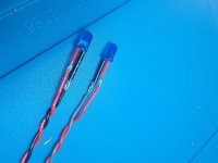
Not easy to see in your pictures, but make sure the power on switch wires are not touching and on the bottom board make sure the Red wire goes to the V+ and Black wire goes to the GND pads.
Not easy to see in your pictures, but make sure the power on switch wires are not touching and on the bottom board make sure the Red wire goes to the V+ and Black wire goes to the GND pads.
Attachments
No shame, we have all done it.
And just a comment, it really will not matter, but the RCA insulating washers look wrong from the pictures. The little ridge (shoulder) on one washer fits into the chassis hole? And a washer either side of the chassis?
Example from the build guide Amp Camp Amp V1.6 Build Guide - diyAudio Guides
And just a comment, it really will not matter, but the RCA insulating washers look wrong from the pictures. The little ridge (shoulder) on one washer fits into the chassis hole? And a washer either side of the chassis?
Example from the build guide Amp Camp Amp V1.6 Build Guide - diyAudio Guides
Last edited:
For future reference,
Put the shouldered washer on the RCA socket with the shoulder going into the chassis. Put the RCA through the chassis and pop the plain washer on. Fit the solder tag and nut(s).
Build Guide steps 28 and 29, one washer either side of the chassis, keeping the metal of the RCA off the chassis. Alan
Put the shouldered washer on the RCA socket with the shoulder going into the chassis. Put the RCA through the chassis and pop the plain washer on. Fit the solder tag and nut(s).
Build Guide steps 28 and 29, one washer either side of the chassis, keeping the metal of the RCA off the chassis. Alan
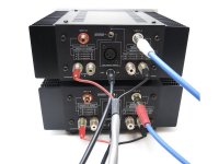
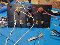
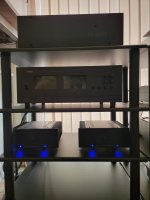
Finished up my second ACA for XLR Dual Mono configuration =)
It was definitely much easier and less anxiety the second time around knowing I have some left over wire from the previous build as well as having it as reference for estimating wire lengths, as well as anything else.
What sounds better than 1 ACA? 2!
Attached are some work in progress pics and their place on the rack amongst their buddies.
If you're wondering, the left ACA has the 1k resistor because, being my first time building anything like this, I didn't put two and two together when I was building it based on the two instruction sets (v1.6 & v1.8).
Attachments
Quote:
Originally Posted by 6L6 View Post
consider a post-SMPS filter… look into rthatcher ‘s CLC filter, or Mark Johnson’s.
Do you perhaps have links to these?
GB - ACA Power Supply Filter Kits
PO89ZB , an inline DC filter for SMPS wall warts . Preamps, HPA, Korg NuTube, etc
Well after fixing the short at the power input socket I spent a significant amount of time trying to figure out why my left channel isn’t balanced with my right channel. I’ve checked that the potentiometer is properly adjusted multiple times, figured out that stereo was the middle and not the top switch (but that didn’t fix the problem), checked the voltage all across the circuit board to see if it’s a problem on the circuit board (though there’s a couple capacitors I can’t check without totally dismounting which I’m trying to avoid), and redid all the soldering attached to ground since I was unhappy with how it came out the first time and visually checked all the other wiring, but to no avail. I do measure a difference in voltage going out to that right side, but I can’t figure out why it’s happening.
- Home
- Amplifiers
- Pass Labs
- Amp Camp Amp - ACA