^^^
Normal and Nothing to worry about. See step 50 of the build guide.
Thanks! I guess I know what step 50 means by "quiet turn on noise" now.

Do you, or anyone have a part#, link or specs for one of these metal illuminated power switch? Seems like this would be a relatively simple change that would upgrade the fit and feel.
Thanks!
Any pics? I just ordered another ACA so will be building another one soon.
Do you, or anyone have a part#, link or specs for one of these metal illuminated power switch? Seems like this would be a relatively simple change that would upgrade the fit and feel.
Thanks!
Any pics? I just ordered another ACA so will be building another one soon.
I wonder if you are all thinking of 'anti vandal' type switches.
Just a note of caution... whatever switch you choose you need to be sure the contacts are suitable for switching the high DC load current of the ACA.
Switching DC current is tough on the contacts and a seemingly suitable switch rated at say 5 or 10 amps AC may be seriously derated for DC capability. You must check any relevant data sheets.
These are the pics that were posted with the thread i quoted. It talked about the correct volts, 230 rated i think?
Would love to have this on my ACA with the color as close to the stock megabrite LEDs as possible. 😀 Anyone have a part number or link?
those style push button power switches are made by Schurter Inc. Digit-Key sells them.
Search for part number 486-1436-ND and then in the results look down the page for other option with internal led's
Search for part number 486-1436-ND and then in the results look down the page for other option with internal led's
I've built the 24vDC DiyAudio PSU V3 for my F5.... still to build the F5 boards though
Post build the PSU tested fine, so I decided to hook it up to my ACA v1.8
Compared against the ACA's SMPS, there appears to be some gains in instrument separation and detail - but really want to readjust the ACA bias before commenting further (-1vDC change on rail with PSU V3).
Anyway, I have a very small hum coming from the speakers when powering the ACA from the V3 PSU. If I disconnect the ACA RCA's, no hum - dead silent, so appears to be a ground loop issue.
Is there anywhere inside the ACA I could ground to stop this hum, or should I try connecting a ground lead between the ACA chassis and the PSU chassis?!?
The hum is very small... have to put my ear right against speaker to hear it
PSU V3..
Antek 5218 Transfo
Vishay rectifiers 35amp 800v
120,000uf total, 55V, 105deg, 5000hrs
PSU C9 cap is not install yet.. I failed to order one (stupid me)
ACA V1.8 (running stereo w/- RCAs)
Thanks
Last edited:
^ sorry should have added..
PSU 240v mains earth connected directly to PSU chassis at IEC mount
PSU 0vDC is earthed to PSU chassis via CL60, earth point is at opposite end of chassis - so not star grounded
PSU 240v mains earth connected directly to PSU chassis at IEC mount
PSU 0vDC is earthed to PSU chassis via CL60, earth point is at opposite end of chassis - so not star grounded
Last edited:
Jeez, USPS "delivered" my ACA components yesterday, allegedly into my mailbox, which is the size of a ream of paper. Last time I checked, a USPS Medium priority box doesn't fit in there unless you jump on the box a few times. I was hoping to experience the ACAs in Dual Mono configuration soon, but it looks like another 8 month battle to get a dime out of them... wonderful!!!!!!!!!!!!!!!!!!!! This is 2 packages they "delivered," but not really delivered in 3 months. Sorry, just venting!
Hi,
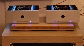
second ACA is finished, measured/adjusted, and now the music flows in RCA-bridged mode - it's just fantastic. The improvement compared to normal stereo is great, there is more body, more detail, deeper lows, clearer mids, crisper highs... I am deeply impressed. And it is just an entry level amp (in the Pass-universe, other would be happy to have it in the normal program 🙂 thank you Mr. Pass!).
Further, in this mode there is no turn on thump. I can't say nothing to turn off because I don't want to turn them off 😀
Attachments
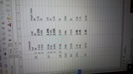
Only just found time to look at my own problem of a few weeks ago. I have checked the supply voltage to both the hot and cold boards, both are 24V as is the voltage on middle pin of Q2. However I'm only getting about 0.4mV across the 0.68 and 0.47 resistors on the cold channel, can anyone tell me what that indicates?Yesterday I thought the left speaker was dropping in and out and checked the amp, one of the heatsinks was stone cold!! I have removed the amp and checked the offset on the cold side, it has dropped to 7.5v, not sure if this is significant but I'm not sure how best to proceed with fault finding?
It said on the guide that the heatsinks have to be warmed up before checking the voltages and as the problem is a cold heatsink I didn't go any further. I did the resistance checks from the same guide and these are attached. The bold values are deviations from the good channel.
Attachments
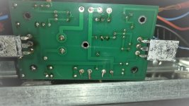
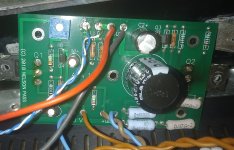
remove bad channel pcb from heatsink, post pictures of both sides
with diode test, check all semis for shorts
if in doubt, desolder and check again
write here, and we'll go from that
with diode test, check all semis for shorts
if in doubt, desolder and check again
write here, and we'll go from that
Hi captain,
there seems to be at least one soldering point which you should check and perhaps re-solder, I mean the positiv leg of the C3 cap. But other soldering points could also endure a review. You could also shorten the wires V+ and LED on the soldering side. It's the first look.
there seems to be at least one soldering point which you should check and perhaps re-solder, I mean the positiv leg of the C3 cap. But other soldering points could also endure a review. You could also shorten the wires V+ and LED on the soldering side. It's the first look.
Agree with shortening the bottom side (solder side) wires. They could be touching the chassis and grounding out.
Not apparent in the picture but they are bent over and not contacting the heatsink but thanks anyway
if you're using non-leaded solder, think of using proper old school leaded solder
did you check any semi with diode test?
did you check any semi with diode test?
No, tbh I'm not sure how to test these once they are in the circuit.did you check any semi with diode test?
- Home
- Amplifiers
- Pass Labs
- Amp Camp Amp - ACA