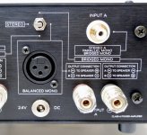
Being a damn greenhorn 😀 I am just confused, when I compare the back panel of the V 1.8 and the description in step 16 in the build guide.
The back panel says for RCA-bridged:
- switch up
- output A - to speaker - (which means A black to speaker black)
- output B - to speaker + (which means B black to speaker red)
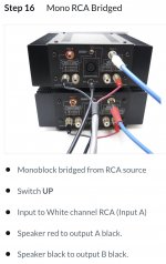
Step 16 says however (and the picture shows it too):
- switch up (okay)
- speaker red to output A black; but it means output A - to speaker + which is the opposit of the description on the back panel
So what is right?😕
The back panel says for RCA-bridged:
- switch up
- output A - to speaker - (which means A black to speaker black)
- output B - to speaker + (which means B black to speaker red)
Step 16 says however (and the picture shows it too):
- switch up (okay)
- speaker red to output A black; but it means output A - to speaker + which is the opposit of the description on the back panel
So what is right?😕
Attachments
I believe the wiring shown in the picture will result in the output being inverted phase to the input. I believe the wiring described on the back panel will result in the output being in phase to the input signal.
Neither is wrong, but you may have a preference. Try both.
Neither is wrong, but you may have a preference. Try both.
Noticed on the chart that captain published, there seems to be a common denominator of something around 2.2 K on the "cold" card. Like there is something that either is a resistor or at least acting like one paralleled across all of those components he lists.
First thought is a short or extreme low resistance across C2 which is the 1000uF cap. The transistor Q3 could be at fault as that is across the cap.
A short between base and collector of Q3 would also do this.
Just checked C2 and Q3, all ok.
Uh...there seems to be more confusion on the rear panel vs. the wiring diagram, and the build guide of the V1.8.
Step 16 (and the rear panel) states, that switch up is the mono RCA bridged mode. When the switch is up then there is a short-cut between the two inputs, which means the same signal for both chanels, and the speaker connection for this mode states, "take the output signal from the both negative outputs for your speaker". However, bridged mode should operate with two "different" signals regarding the phase, which is here not the case, not on the input and not on the output. This mode should be called "parallel mono". In parallel mono mode however the two outputs should be switched together - as shown in step 17 for mono RCA parallel with jumper between both black speaker posts.
With switch down (called "parallel mono" on the rear panel and in step 17) input A (left channel) gets the input signal according to the wiring diagram, while input B (right channel) will be driven from the output of the left channel via the 39K resistor - and yes, this signal is inverted (as the amp inverts the signal between input and output), which means THIS is the bridged mode of the switch, not the parallel 😕 And in this bridged mode, the speaker should be connected as shown in step 16 for the bridged mode.
I think, the 39K resisitor should be connected to the upper right contact of the switch instead of the lower right and the short-cut should be between the two lower contacts.
Please check it too, compare the wiring diagram with the rear panel and the speaker connections.
Last edited:
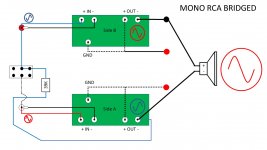
When the switch is up, there is not a shortcut between the inputs. See below for a simplified diagram. Also, when using it in RCA-bridged, you only connect the input signal to "Side A". The terminology and the wiring are correct to the best of my knowledge.
Attachments
Please take a look at the wiring diagram in the link, which shows the change between V1.6 and V1.8. There is a short-cut and according to the build guide and the rear panel this is the bridged mode, which is not the case.
https://d17kynu4zpq5hy.cloudfront.net/igi/diyaudio/sB2CTXYJABd5XxLP.huge
And here the picture of the mounted switch: https://d17kynu4zpq5hy.cloudfront.net/igi/diyaudio/tMAFirRhuraCkTLC.huge
https://d17kynu4zpq5hy.cloudfront.net/igi/diyaudio/sB2CTXYJABd5XxLP.huge
And here the picture of the mounted switch: https://d17kynu4zpq5hy.cloudfront.net/igi/diyaudio/tMAFirRhuraCkTLC.huge
Last edited:
The short-cut is not there when the switch is in the up position. Perhaps trace it with your DMM.
Edited to add - I think I perhaps understand your confusion. When the "outside" / actual switch is up, which contacts are engaged on the inside / back of the switch?
Edited to add - I think I perhaps understand your confusion. When the "outside" / actual switch is up, which contacts are engaged on the inside / back of the switch?
Last edited:
Just checked C2 and Q3, all ok.
I am able to get most of the oddball measurements that you show on your chart by shorting the center pin of the 5K pot to the first terminal. (The one not at ground). Is the pot, P1 perhaps shorted internally?
Thank you - my bad, sorry. Switch down is the short-cut, the switch works "reversed".
Sorry for the confusion 😱
Sorry for the confusion 😱
Ask me how I may have known that could be the cause of the confusion….
Did you fall into this "trap" too? 🙂
I am ashamed...

I sure did. That’s one of the reasons I did a full set of diagrams similar to the one I attached earlier. It took me far too long to work it out without a visual representation and showing the phase of the signal as it moved from input to speaker.
Good idea 🙂 Thanks for opening my eyes 😀
The 30 years long brake from building audio equipment shows a clear effect 😛
The 30 years long brake from building audio equipment shows a clear effect 😛
So what is right?😕
Whoops!
The photo is incorrect, the panel instructions are correct. Speaker connections are different with self-bridged (RCA) vs XLR bridged. Sorry for the confusion, I’ll fix that.
if you're using non-leaded solder, think of using proper old school leaded solder
Agree with that. It seems that the solder has not fluxed nicely, it is grainy and that means that the contcts will be haphazard, maybe even changing contact during a warm-up and cool-down period.
I once bought a nice roll of silver solder in China, but it was one for factories for above 400 degrees, only fit for their fast very high temp soldering and special irons. It cost me my appetite for DIY for several years (everything I built broke down after some time...) and it was very bad for my temper.
Using such solder we only mess things up.
> Buy low temp solder. Low melting point, even under 300 degrees.
Noted.It seems that the solder has not fluxed nicely, it is grainy and that means that the contcts will be haphazard, maybe even changing contact during a warm-up and cool-down period.
As always plenty of people have chipped in with suggestions for my little problem and I am very grateful for that. My progress is painfully slow as I am scratching around for spare time at the moment so bear with me!
It is interesting that the help seems to fall into 3 basic categories;
1. Systematic measurement and fault finding.
2. Reflow all solder.
3. Remove and replace all transistors.
All of these approaches have their merits for me but I would like to get to the bottom of what went wrong.
I am a great believer in measurement 🙂
Can you do one quick check (if not already done) and that is with the amp OFF can you measure the resistance between G and S of Q2. Try it with your meter leads both ways around.
Does it read very low? Use a low ohms range and not the diode check range.
Can you do one quick check (if not already done) and that is with the amp OFF can you measure the resistance between G and S of Q2. Try it with your meter leads both ways around.
Does it read very low? Use a low ohms range and not the diode check range.
- Home
- Amplifiers
- Pass Labs
- Amp Camp Amp - ACA