
But, how would I translate this into „horsepower“ [emoji1320] ?
= how do I get a feeling of how much torque I am applying through the screwdriver/wrench, or even better, is there a method to kind of approximately measure it without expensive torque-wrench?
Something like (hypothetical): when tightening an M3 with a specific) wrench, 1.1 N/m are applied when the wrenches edge is 5mm into the pushing finger. Or, more objectively, whe screwing an M3 into a 5mm MDF, 1.1 N/m are needed to ‚overtighten the thread‘
If we had some approx measures like these to adjust the touch+feel…
1.1 N/m is 0.8 foot pounds so a good approximation is a 1pound or 454 gram weight suspended off the end of a 12 inch/30cm ruler. Its pretty close.
Hold the other end of the ruler and it lets you gauge what that level of torque feels like.
If you have a socket set with a 30cm handle then dangle the weight off the end and let that alone tighten the nut.
It's probably a lot less 'tight' than you think.
Hold the other end of the ruler and it lets you gauge what that level of torque feels like.
If you have a socket set with a 30cm handle then dangle the weight off the end and let that alone tighten the nut.
It's probably a lot less 'tight' than you think.
ZM is one of most stubborn Greedy Boyz I know
and, believe me - I know him
but, recently ZM was searching and, instead of relying on own extrasense, he's now having 2 torque screwdrivers - one set to 0.9Nm (M3) and second to 1.3Nm (M4)
in praxis - without torque measurement - taking care of pad used (softer are more critical) - tighten just to squash split washer
there is a risk, but with small number of screws - risk is small
if you are dealing with greater number of screws, risk of seeing Gremlins in action is increased
Or in other numbers, 2724 gr at the end of a 5 cm inbus-wrench, (or 13620 gr at the handle of a screw-driver) is this correct?
Which seems reasonable, although 13kilos is a bit frightening [emoji41]
Which seems reasonable, although 13kilos is a bit frightening [emoji41]
Recommended torque for the M3 screws is 8 inch-pounds. I use a torque driver. The feeling is one of firm finger tight with a standard size screwdriver handle.
Stereo input, mono output?
I am finally getting around to building my 1.6 kit. I will be using it in a small room (10'x9') so was thinking about using a single speaker. Since it isn't built yet, is there an easy way to have stereo input (from phone) and mono output?
TIA, Rick
I am finally getting around to building my 1.6 kit. I will be using it in a small room (10'x9') so was thinking about using a single speaker. Since it isn't built yet, is there an easy way to have stereo input (from phone) and mono output?
TIA, Rick
Yes easy.
Build it like the v1.6 guide then run the outputs in parallel mode.
Link the two Black speaker terminals together with a wire. The Reds are already connected internally. Just use one Black and one Red speaker terminal to connect to your mono speaker.
There is a post #6514 here. If you click on the blue arrow it will take you to the post with pictures.
As you have a stereo input, there is no need to link the inputs at the XLR connector.
The only issue you might /will have is that most phones and ipads do not have enough output to give good volumes with the ACA. You will likely need a preamp as well.
Alan
Build it like the v1.6 guide then run the outputs in parallel mode.
Link the two Black speaker terminals together with a wire. The Reds are already connected internally. Just use one Black and one Red speaker terminal to connect to your mono speaker.
There is a post #6514 here. If you click on the blue arrow it will take you to the post with pictures.
There have been a couple of pictorials posted before, this one is easiest to do and understand by Mutuano. It is all external and easily reversible too.
Link the two Black speaker connections with a wire. (The Red ones are already joined internally.)
If you have wired the rear switch from the build guide step 38, make sure it is Down as in the pictures.
That's it.
As you have a stereo input, there is no need to link the inputs at the XLR connector.
The only issue you might /will have is that most phones and ipads do not have enough output to give good volumes with the ACA. You will likely need a preamp as well.
Alan
One channel working is good as it allows you to compare.
If the FET's are about equally hot between channels and whilst also having a DC voltage of about 12 volts on the plus end of C1 (speaker coupling cap) then that is pretty good proof all the DC conditions are OK and the problem is most likely down to input or output wiring.
Hi Mooly. Both FETs are hot. Do I ground while checking C1? Also, I’ve stupidly soldered the C1 cap flat on the board so can’t get to it. Do I need to take the board off or can I check this another way?
All voltage measurements are done with the black meter lead connected to ground. If you can not get to C1 directly then measure the voltage at the junction of R1, R2, R3 and R4. Look at the circuit and you will see that point goes to the + end of C1.
Attachments

Thank you so much for taking the time to help me. I always knew the learning would start properly with a problem. 🙂
Thanks Alan. I think I've got it. It helped when you equated (in another post) bridged to serial vs parallel. I also found another post of yours (7947) that further explained the various modes.
Agreed, I might need to boost the input but that can wait until I finish building the amp!
Agreed, I might need to boost the input but that can wait until I finish building the amp!
Thank you so much for taking the time to help me. I always knew the learning would start properly with a problem. 🙂
It's no problem 🙂 and if the DC conditions do check out OK then we are looking more at wiring errors with the amp input and speaker output side of things.
Just work through that check list and see how you get on 🙂
Yes I would imagine it’s a soldering issue. I couldn’t get the iron to tin properly with this amp (1st one was built much better) and I had soldering issues right the way through.
My solder sucker arrived in the post today (Cork, Ireland literally has nowhere to buy accessories) so I’m going to re-do those areas you mentioned as I had the most problems with those. Once I know they’re done properly, I will get through the trouble shooting list you provided.
🙂
My solder sucker arrived in the post today (Cork, Ireland literally has nowhere to buy accessories) so I’m going to re-do those areas you mentioned as I had the most problems with those. Once I know they’re done properly, I will get through the trouble shooting list you provided.
🙂
what I do often is resolder, make it hot, add a quarter-mm of solder tin and then with the iron go up and down. This makes a bad joint flow again.
depends also on the solder you have.
Note
As said, we assume a lot of things can go wrong . . .
depends also on the solder you have.
Note
- Some solder is for very high temp irons, for factories. For amateurs it is bad bad, gives loose joints.
[I lost over two years work due to recurring bad joints in DACs. Finally I bought good traditional SAVBIT solder and things go god again....]
As said, we assume a lot of things can go wrong . . .
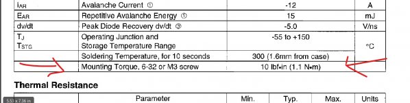
Torque figures are often given in data sheets and it can be surprisingly low.
Hi Mooly,
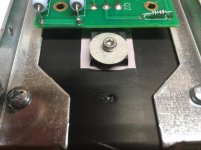
I have a torque screwdriver that was set for 10 in lbs when I installed the screw holding the transistor. The thing is, the torque figure in the transistor data sheet gives you the maximum before stressing the part. What we want to know is the maximum torque you can put on the Keratherm part before it deforms. I have looked at the Kerafol "Keratherm® Red" data sheet and it contains no information on this.
On a side note: I'm working through your LtSpice tutorial which is very helpful! thanks!
- Home
- Amplifiers
- Pass Labs
- Amp Camp Amp - ACA