Fantastic help guys thanks. So this is the 1.8 with power switch on front and bridged.
Indeed I forgot the heat shrink on the LED’s. I don’t think they are shorting though but I’ll fix that.
In terms of starting with the basics, I’m a complete newbie here. To check the terminals with my multimeter, how do I do that?
Indeed I forgot the heat shrink on the LED’s. I don’t think they are shorting though but I’ll fix that.
In terms of starting with the basics, I’m a complete newbie here. To check the terminals with my multimeter, how do I do that?
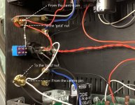
1.8 back panel wiring (from build quide):
OK. I’ve wired both up wrong then. I’ve been using the first amp in stereo the last few weeks and it’s working perfectly though. When I tried that with the second one, it didn’t work so I’ve probably got a few issues going on here 😎
...
In terms of starting with the basics, I’m a complete newbie here. To check the terminals with my multimeter, how do I do that?
Easy,
Switch your meter to the 2KΩ range, you're measuring resistance, then put the black probe in the black speaker terminal and the red probe in the red speaker terminal. You have to touch the metal parts. See what your meter reads. Do both sides.
Next switch the meter to 200kΩ range. Now put the black probe on the gold outer ring (RCA socket) and then put the red probe in the centre of the RCA socket. Again touch the metal parts and record the reading from the meter. Do both sides again.
Might be an idea to look over a couple off tutorials on using a multi-meter too. Did you do the bias voltage set up?
Do these tests with the power disconnected.
It will not matter that the rear switch is wired as you have it. You just loose the 'parallel mode', the 'bridge mode' still works the same as the v1.6 build. That is with the switch up on both amps.
I'll be ordering an ACA soon. Just waiting for the summer heat to cool down a little.
I was just wondering how the ACA compares to the other First Watt Clone kits - listening sound wise. I understand that the F5/6 has a few more watts, but with the ACA in dual mono then it's a in the ballpark match.
I was just wondering how the ACA compares to the other First Watt Clone kits - listening sound wise. I understand that the F5/6 has a few more watts, but with the ACA in dual mono then it's a in the ballpark match.
Sunscreen,
I am sympathetic about waiting to fire up the soldering iron. I figure I have about two or three hours at most to finish the board I'm currently working on this morning.
The ACA is best with fairly efficient speakers. My speakers are the old Vandersteen 2C, and a single ACA showed signs of compression fairly early. It wasn't until I did my modifications and eventually ran with two bridged ACA monoblocks that I came to appreciate what the little amp is capable of.
That said, I have moved most of my builds into the 25 Watt range, as there are a number of benefits to having more power available. The exception is the new DIY Sony VFET 'lottery' amp, which delivers well above its nominal power rating.
Hey Alan4411.
I did the tests you said to do.
Speaker output B reads 989
Speaker output A reads 775 but creeps up to 975 over 60 seconds or so ( was still creeping up after but very slowly)
Couldn’t get any reading from either RCA inputs. I tried outside and inside but got nothing.
I haven’t done the bias yet. I will do that next.
AlexJones said:Speaker output B reads 989
Speaker output A reads 775 but creeps up to 975 over 60 seconds or so ( was still creeping up after but very slowly)
Couldn’t get any reading from either RCA inputs. I tried outside and inside but got nothing.
The speaker readings are fine. That's good.
I do not understand ''Couldn’t get any reading from either RCA inputs''.
Do you mean they are open circuit or short circuit?
Look at the picture I've posted, meter on 200k ohm range and put one probe on the centre pin (where the red and white wires go) and the other probe on the nut. Try again. If possible post a picture of the readings you get?
Did you set the bias on the previous ACA you built?
Alan
Attachments
The meter doesn’t change when I do the RCA inputs. It reads “1”.
I did the bias on the first amp, yes.
I did the bias on the first amp, yes.
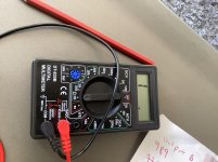
That is just out of range on the meter. Its set to 200 ohms.
You need to set the knob so it points to the 200k setting (3 clicks clock wise...) and try again.
You need to set the knob so it points to the 200k setting (3 clicks clock wise...) and try again.
Alex, you are getting some great advice here but can you work through this list and see where it falls down 🙂
You have to begin with the most basic tests and that begins with supply voltage and the DC conditions. I just can't spot anywhere where you have done that.
1/ The supply voltage of 24 volts has to be correct entering the board (or as measured on the middle lead of Q2). Be extremely careful not to short to the other leads when checking.
2/ The FET's and the heatsink should be hot after a few minutes. The voltage measured across any one of the 0.47 ohm resistors should be about 0.37 volts. The voltage across either 0.68 ohm should be about 0.55 volts.
3/ The voltage on the plus end of C1 (the big 3300uF speaker coupling cap) should be about 12 volts and be adjustable with the preset.
4/ The positive speaker socket should read zero (0.00) ohms to ground.
5/ The negative speaker socket should read zero (0.00) ohms to the negative end of C1.
6/ The outer part of the RCA socket should read zero (0.00) ohms to ground.
7/ The inner connection of the RCA socket should read zero (0.00) ohms to one side of R11.
8/ There should be no short between inner and outer of the RCA. You should see higher than 10k here.
9/ There should be no short between the positive and negative speaker sockets.
Note.
0.00 ohms is a short but your meter will probably show something a little higher due to lead resistance, for example 0.2 ohms if you short the probes together on the low ohms range.
All these tests also assume that 'ground' is OK and that the 0 volt line of the power supply is connected correctly. The common point on the PCB that R14, R9 and the Source of Q1 connect to is 'Ground' for measurement purposes.
Thanks, I plan on eventually using mono's at some point. Right now I use a 22 watt EL84 amp that effortlessly drivers my Zaph Audio SR71 speakers.My speakers are the old Vandersteen 2C
I eventually ran with two bridged ACA monoblocks that I came to appreciate what the little amp is capable of.
That said, I have moved most of my builds into the 25 Watt range.
However, I was wondering about the "sonic" differences between an ACA and say, the First Watt F6.
BTW what modifications did you do? The only ones I've even considered were "maybe" replace the two caps in the audio path with Nichicon's. But I have no idea it really is an upgrade from the caps supplied with the kit?
Just caps
Thanks, I think I'll just upgrade the signal path caps to the Nichicon just for "peace of tweakers mind". I'm not looking to as much to upgrade, but learn and enjoy. I've built and tweaked enjoy for two life times.
thanks
Thanks, I think I'll just upgrade the signal path caps to the Nichicon just for "peace of tweakers mind". I'm not looking to as much to upgrade, but learn and enjoy. I've built and tweaked enjoy for two life times.
thanks
The little Elna Silmic on the input is actually one of the best available. The output cap be increased to 4700 uF. I still like the Nichicon KG series for this.
I'm listening
I'll only change the 4700uf cap to a Nichicon. I have no burning desire to reinvent this amp.
thanks
I'll only change the 4700uf cap to a Nichicon. I have no burning desire to reinvent this amp.
thanks
upon review
I was looking for a KG series cap. Maybe I'll just use the stock parts and enjoy it as Nelson P intended.
I was looking for a KG series cap. Maybe I'll just use the stock parts and enjoy it as Nelson P intended.
- Home
- Amplifiers
- Pass Labs
- Amp Camp Amp - ACA