Hi Chris,
....
And I'll share a little secret here:
my next amp (which is almost ready) is ACA with 44V supply, similar to Tony Tecson's. That will be something.
well ....we are waiting

Last edited:
Measure at the resistor leg connected to it, R10 - R6/R9.... the problem with this clone pcb is that its really wiggly to get a measurement at the Jfet and the bipolar. its so closed together. i will try it....
ACA is not very happy with 4R, no matter how well behaved the impedance is.
Parallel channels would be happy with 4Ω
dave
Finally, I finished an ACA last night which has been in the making for a some time. It was a project my friend started with the intention that I would help coach him through the build. It was hard to find common spare time, and he got a little frustrated when we got to the wiring stage, so he just handed it off to me for final assembly.
I'm blown away by the sound of this little amp. In my system it outputs to a pair of 91.5dB conventional speakers and is driven by a Pearl II/Korg B1 combo. I'm listening at a pretty good volume seeing peaks at my listening spot of 79dB. It sounds way more powerful than I ever expected from an 8 watt amp. I've built a few Firstwatt clones (F5, F4, M2, M2X), but at the moment this is my favorite Nelson Pass design. It just brings something different to the table compared the others. There are numerous glowing reviews of the ACA...they are true.
If you're sitting on the fence about this amp, get off and BUILD IT. It's a ton of fun and sounds fantastic.
I have a small question, I would like to build 4 ACA channels in one box and use XLR or RCA inputs. In the build guide (1.6) is stated that if you use the ACA1.6 as a mono box with balanced inputs the switch on the back should be down, and if you use the amp as a mono box with the rca input the switch should be up.
If the switch is in the up position, can't the amp be used with the XLR input?
so the short question is... do i need switches?
Cheers, Neel007
been there done that.....it is entirely doable...
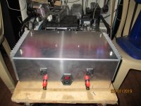
Attachments
Measure at the resistor leg connected to it, R10 - R6/R9.
here are my voltages
i measrued both MOSFET
Q1 G 4,76V, 4,68V D 8,72 8,71 S 0,001v, 0V
Q2 G 14,28V 14,31V D = supply 23,82V S 9,67, 9,67
N JFET
Q4 G 4,85 4,74 D= supply 23,82V S 4,72 4,67
Last edited:
...about Q4
indra wrote at 9411:
@chermann - You are concerned by the gr grade you have. Measure Vgs of jfet to make sure it is less than +0.5V in the ACA. It will not be a large value even if negative for a 2sk30gr. The channel that shows early negative clipping may show Vgs of jfet close or even higher than +0.5V. In that case, it makes sense to replace it with higher Idss part.
so with Gate
4,85V and Source 4,72V i have a different of Vgs= 0,13V .................so everything is fine??
Last edited:
Q4 G 4,85 4,74 D= supply 23,82V S 4,72 4,67
So Q4 Vgs
4.85 - 4.72 = 0.13
4.74 - 4.67 = 0.07
Most probably the one with Vgs = 0.13 is the one giving you earlier clipping, both are usable but are not ideal since we actually want a slightly negative Vgs.
If you want maximum possible output, I'd suggest replacement of both Q4 with matched 2SK246BL, or better yet the LSK170B from the store.
Edit:
For a stopgap measure, you can try increasing R9 to 1.2 - 1.5k.
Last edited:
Different grades (Vgs) of FET will just mean the preset has to be altered in its setting and as such it should cope with some pretty wide differences.
If the preset is about central in its range then Vgs is probably similar to the originally specified part (2SK170). If the FET is one ended and turned more toward ground then that is because Vgs is going to be higher.
If the preset is about central in its range then Vgs is probably similar to the originally specified part (2SK170). If the FET is one ended and turned more toward ground then that is because Vgs is going to be higher.
Can R12 be changed in value to give a higher output impedance, say closer to 2.5 ohms?
Increasing R12 will increase the output impedance but it does so at the expense of higher gain and higher distortion. You would need to go to around 180k to get 2.5 ohms output impedance and the gain would shoot up to about 23db
Mooly, chermann is using a 2SK30GR at Q4, Vgs is going to be positive operated with Id > Idss.
Is that a problem though?
Id of the FET is running around 5ma to bias the ACA up correctly. It shouldn't matter within reason where Vgs of the FET is at as long as it is in adjustment range of the preset.
A wide range of Vds values should all work and the final Id once set up will be the same for all.
Hi
so at Q1 is following:
i have about 4,8V Vgs and a current of about 1,6A. if i look at the datasheet at 150°C and not the diagram with 25°C i can estimate that? pic with red
should it not be better to have much more Vgs to be in the linear area? 2nd pic green
thank you for your help again
chris
so at Q1 is following:
i have about 4,8V Vgs and a current of about 1,6A. if i look at the datasheet at 150°C and not the diagram with 25°C i can estimate that? pic with red
should it not be better to have much more Vgs to be in the linear area? 2nd pic green
thank you for your help again
chris
Attachments
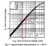
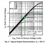

chermann,
The horizontal axis is Vds. Assuming your V+ is 19V, Vds of Q1 is approximately half of 19V, so you are in the linear region. You show Vds of less than 2V on your charts.
Also 150C is most likely not representative of the temperature of Q1. Your Vgs is higher due to the actual temperature of Q1 which I assume to be much lower than 150C.
- Home
- Amplifiers
- Pass Labs
- Amp Camp Amp - ACA