...waiting for other jfets...
Hi
last days i enjoy sounding my new speakers "Nada" and my other amps and for sure the ACA.
i miss a bit the deepness and separation in the middle and its partly "foggy" compared to my other amps.
i tried the NFB resistor (R12) to get 39k but with my 81k in parallel with 68k i got about 37k..Gain is about 2,5 and about 8,5dB. i just want to listening and try out something.i have still the topic with the unsymmetrical output. with my 4R speakers i have to go up to 24V to avoid some clipping at some peaks. after setting the DC bias to 9,1V each i get best result on "symmetry" i can have with this setup. (BC550C Q3, and K30A as JFET)
sound is better...separation and dynamic improvement. i think i got at the unsymmetrical setup often then i thought a soft clipping.
problem here is that with DC bias at 9,1V the Q1 have to waste about 15V and 1,6A and it gets very hot without signal....90°C😱...during playing its better but during compare with other amps its not a nice feeling that Q1 is getting ..*x(! ..hot😱
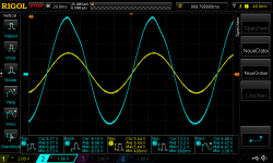
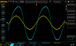
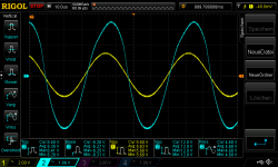
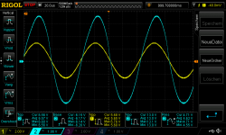
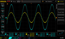
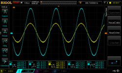
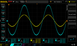
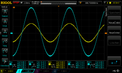
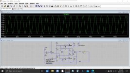
here are the Frequency response curves with 1,910Vrms input and max output before clipping. still a bit un-symmetric but its the best i can have. both channel have the same behavior.
pic 1-9
10Hz, 100Hz, 1khz, 3kHZ, 6khz, 12khz, 15khz, 21khz, 35khz
waiting for ZTX450 and as JFET i will get BF245B...hopefully better symmetrical adjustments possible
chris
Hi
last days i enjoy sounding my new speakers "Nada" and my other amps and for sure the ACA.
i miss a bit the deepness and separation in the middle and its partly "foggy" compared to my other amps.
i tried the NFB resistor (R12) to get 39k but with my 81k in parallel with 68k i got about 37k..Gain is about 2,5 and about 8,5dB. i just want to listening and try out something.i have still the topic with the unsymmetrical output. with my 4R speakers i have to go up to 24V to avoid some clipping at some peaks. after setting the DC bias to 9,1V each i get best result on "symmetry" i can have with this setup. (BC550C Q3, and K30A as JFET)
sound is better...separation and dynamic improvement. i think i got at the unsymmetrical setup often then i thought a soft clipping.
problem here is that with DC bias at 9,1V the Q1 have to waste about 15V and 1,6A and it gets very hot without signal....90°C😱...during playing its better but during compare with other amps its not a nice feeling that Q1 is getting ..*x(! ..hot😱
here are the Frequency response curves with 1,910Vrms input and max output before clipping. still a bit un-symmetric but its the best i can have. both channel have the same behavior.
pic 1-9
10Hz, 100Hz, 1khz, 3kHZ, 6khz, 12khz, 15khz, 21khz, 35khz
waiting for ZTX450 and as JFET i will get BF245B...hopefully better symmetrical adjustments possible
chris
Attachments
-
 R_24Vsupply_NFB37k_Gain2,54_in1910mVrms_10hz.png49.8 KB · Views: 286
 -
 R_24Vsupply_NFB37k_Gain2,54_in1910mVrms_35kh.png45.4 KB · Views: 75
 -
 R_24Vsupply_NFB37k_Gain2,54_in1910mVrms_21kh.png49.4 KB · Views: 76
 -
 R_24Vsupply_NFB37k_Gain2,54_in1910mVrms_15kh.png52.9 KB · Views: 78
 -
 R_24Vsupply_NFB37k_Gain2,54_in1910mVrms_12kh.png50.6 KB · Views: 77
 -
 R_24Vsupply_NFB37k_Gain2,54_in1910mVrms_6kh.png52.9 KB · Views: 274
 -
 R_24Vsupply_NFB37k_Gain2,54_in1910mVrms_3kh.png53.2 KB · Views: 285
 -
 R_24Vsupply_NFB37k_Gain2,54_in1910mVrms_1khz.png49.6 KB · Views: 281
 -
 R_24Vsupply_NFB37k_Gain2,54_in1910mVrms_100hz.png49.9 KB · Views: 281

Hi Mark
do you mean that the gain is too low, that the input signal is to high and therefore i have to use higher gain, e.g. 4,5 gain as original?
chris
do you mean that the gain is too low, that the input signal is to high and therefore i have to use higher gain, e.g. 4,5 gain as original?
chris
Hi
i try to learn and read about 473 page the last weeks and make some notes.😀
i really do my best to understand but ...😉
i read a lot of comments by Loudthud (he is really very good in explaining ..but I am to mud in my head to understand completly...) and he stick to leave the Feedback Resistor R12 away... ony body try this?
is this feasible at LT spice?
chris
...idss tooo low?
According to the post #861 page 87
https://www.diyaudio.com/forums/pass-labs/215392-amp-camp-amp-aca-87.html#post3427257
....If Q4's Idss is less than 4.5mA, it's Gate to Source voltage would go positive before there is enough Gate voltage at Q1. So a Toshiba GR grade part (Idss 2.0 to 6.5mA) might not work in the circuit as designed...
can that be that my K30A is too weak to get enough current ? i looked at my K30A the have labeled GR...but not as written in the datasheet 035G...so its a different version and that is the bad i guess
Attachments
hi indra
i thought that the gate must be like:
also in post 861
Q4's Gate to Source voltage can't be more than (minus) 4.5V or Q4's gate voltage would need to be below ground (and thus P1 could net be set)
i thought that the gate must be like:
also in post 861
Q4's Gate to Source voltage can't be more than (minus) 4.5V or Q4's gate voltage would need to be below ground (and thus P1 could net be set)
Reduce input amplitude by 50%.
Who, me?
😀
Hi
................and he stick to leave the Feedback Resistor R12 away... ony body try this?
is this feasible at LT spice?
chris
Do you mean to run it without any resistor at all in that location?
Dear Mooly, author of post #9402 showing impure sine wave simulation output when driving simulated B&W703 load model:
I think you will get different (better) looking output, if you reduce the input amplitude to your simulated amplifier, by 50%. Perhaps I think wrongly.
I think you will get different (better) looking output, if you reduce the input amplitude to your simulated amplifier, by 50%. Perhaps I think wrongly.
@chermann - You are concerned by the gr grade you have. Measure Vgs of jfet to make sure it is less than +0.5V in the ACA. It will not be a large value even if negative for a 2sk30gr. The channel that shows early negative clipping may show Vgs of jfet close or even higher than +0.5V. In that case, it makes sense to replace it with higher Idss part.
Dear Mooly, author of post #9402 showing impure sine wave simulation output when driving simulated B&W703 load model:
I think you will get different (better) looking output, if you reduce the input amplitude to your simulated amplifier, by 50%. Perhaps I think wrongly.
Here you go 🙂
Attachments
Amp Camp Amp 39.2 kohm resistor
Newbie here and I'm building the ACA but have misplaced/lost just one of the 39.2 k ohm resistors. Don't know what the values of this wayward resistor I'm looking for and where can I get just 1 on-line. Suggestions? Thanks!
Newbie here and I'm building the ACA but have misplaced/lost just one of the 39.2 k ohm resistors. Don't know what the values of this wayward resistor I'm looking for and where can I get just 1 on-line. Suggestions? Thanks!
It is a 39.2k ohm or 39200 ohm resistor or sometimes written 39k2.
A 39k (so 39000 ohm) would would be fine to use if you can't locate a 39.2k but for completeness fit the same value to both channels. It will alter the gain by a tiny tiny tiny amount.
Should be available from any component supplier. You want a 0.5 or 0.6 watt metal film part of 1 or 2% tolerance.
Cost is almost zero but ordering one offs like that will hit you with minimum order and delivery charges.
It is a 39k ohm 0.5 or 0.6 Watt metal film resistor. (Do not worry about the 39.2k)
Not sure you will be able to buy just one. Perhaps some kind member can send you one or get a small packet from ebay or similar?
edit Like he said ^^^...
Not sure you will be able to buy just one. Perhaps some kind member can send you one or get a small packet from ebay or similar?
edit Like he said ^^^...
Last edited:
Mooly, like Captain Renault in "Casablanca", I am shocked. Shocked to see that reducing the output current demand by 2X, improves the amplifier linearity.

..
Do you mean to run it without any resistor at all in that location?
post 614
You could just leave off R1 and R3 and that would cut the current in half. I suspect the distortion would increase because Q1 would be farther into it's non-linear zone and open loop gain would be reduced. The distortion will be low order, you might actually like the sound. I like listening to mine with the feedback disconnected. Just remove R12. My latest build (#6) has a pair of IRF520s. They have a flatter distortion at 1W graph.
post 666
..... To maintain the distortion character of the amp, changes to the amount of feedback are needed. I recommend you look at the PLH article: http://www.passdiy.com/pdf/PLH_amplifier.pdf
post 864
The -V parts will work because of the high Yfs and low Vgs(off) of the 2SK170. I experiment with things like R9 just to see if I can hear or measure the difference. Most times I can't hear it, unless the feedback is disconnected.
in the thread ACA with premium parts the schematic is change to 20k input resistor and the Rf is 90k.
sorry to be nooby , but i read now a lot and i want to be clear what is useful for better sound.
chris
@chermann - You are concerned by the gr grade you have. Measure Vgs of jfet to make sure it is less than +0.5V in the ACA. It will not be a large value even if negative for a 2sk30gr. The channel that shows early negative clipping may show Vgs of jfet close or even higher than +0.5V. In that case, it makes sense to replace it with higher Idss part.
Hi indra1
thanks you for that information.
the problem with this clone pcb is that its really wiggly to get a measurement at the Jfet and the bipolar. its so closed together. i will try it.
just to be clear:
at scope you see the "bad" negative wave but its in real the other way round = inverted. so in real the negative wave is ok and the positive is "bad"
chris
- Home
- Amplifiers
- Pass Labs
- Amp Camp Amp - ACA