RF,
R123/C121 flatten the loop gain of the amplifier from 500Hz to 18KHz, and increases it from 22.8db to 45.8dB (see the graph) at very low frequencies. This gives the AN very strong bass performance. Lower loop gain increases distortion, but not as much as you would expect from the 45.8db drop to 22.8dB. The reason is that it is nested fb, and it improves the linearity of the amp for all stages BEFORE the output stage. This ameliorates the resulting loss of lower loop gain, and it does increase THD by about three or four times, but slightly reduces higher orders, bringing up H2, H3 and H4, which are moderately musical. Over 99% of the THD of this amp is H2, H3 and H4.
You can disconnect either the R123, OR C121 to remove this feature. If you do this, you will notice a difference in sound quality. Most people prefer nested fb but it is controversial because THD is higher. Try it, have a listen, try to figure out WHAT it changes! NFB has been described over the decades, including by Cherry, but it has not been examined from the subjective POV for audio amplifiers. Objective results are BAD, but subjective results are very good. This opens a can of worms and has attracted trenchant criticism. I do not claim that the THD figures are good, but then, audio is entertainment and my builders love my amps regardless of the figures.
Below is the Tian probe loop gain WITHOUT nested fb.
HD
Attachments
Last edited:
Thank you! Just what I was after 🙂
I know measurements are not everything (or I just can't interpret them well enough), and I would like to experiment by tuning the amount of nested feedback and the frequency of the pole.
I have a basic Yamaha stereo amp in the garage that I did some tweaking to, and it measures really good, but still the sound is.. ok, but not as good as the JLH. I also built a lot of chinese kits etc, and tried to improve/modify those, and some commercial amps too.
I think the only conclusion so far has been that improving measurements on a specific amp, has made it sound better to me, but I can still like another amp more, even if it measures worse. For loop gain, I have a feeling that low loop gain gives smoother sound, high loop gain tighter bass.
I lifted one end on the R123 today to test. I ran the amp on the garage speakers during the day, and I think it sounded a bit more forward. Possibly I liked it better as it was before on those speakers.
I have just started to listen at home now, and I think it sounds a bit more balanced on the speakers I have at home, the impression I had before was that it was a bit 'fat' in the low end at home, and maybe a bit recessed/not so detailed in the mid/high. Need to give it some time with varying music, and to see if it starts irritating my ears.
Plus side on the cap-mx for the front end is less turn on thump. Cant hear it now, I only see the woofers moving slowly, and not very much.
Just thinking out loud while listening.. maybe I should connect a switch for the R123/C121 on the amp. Open position named crystal, diamond, or something like that, the other something soft and cozy.., velvet? 🙂
For those who have built the amp and feel like experimenting, try lifting one leg of one of the above to open the circuit of the nested feedback, it does things to the sound.. Whatever you prefer is a matter of taste, just like most things in life 🙂
For those who have built the amp and feel like experimenting, try lifting one leg of one of the above to open the circuit of the nested feedback, it does things to the sound.. Whatever you prefer is a matter of taste, just like most things in life 🙂
F3 has pot for the amount of feedback...and it makes a big difference. I was thinking about making the pot on the front for easy adjustment while playing.
Just to make ZM jump out of his skin, since he called it idiotic.
I do not have time to work on AN39, I am too busy playing with tube pre, maybe be later.
Just to make ZM jump out of his skin, since he called it idiotic.
I do not have time to work on AN39, I am too busy playing with tube pre, maybe be later.
I did some measurements of the amp today, tried to compare it with and without the nested feedback, but the diff was within a few dB (with distortion in the -80dB range depending on power level and frequency), and distortion character stayed the same. No significant changes in that respect.
Distortion is just as advertised, dominant H2 and falling. I noticed that distortion rises with frequency, as seen in the multi-tone test. I did not expect that since loop gain is pretty flat in the audio spectrum, and there is no crossover distortion either. I also noted that distortion went up significantly with 4ohm's load, even at low output levels (not current limited), luckily my speakers are an easy load.
This is the multitone with nested feedback (L & R channel overlaid). Same setting as 10V sine, a bit hard to define power or voltage, I think peaks are the same level as peaks on a 10V sine, so fairly high power output. At lower output, the rise in the high frequencies disappeared into the 'distortion floor' so I guess the conclusion is that distortion rises more in the top end with more power output/current modulation.

Here is the distortion at 10V sine output, nicely falling harmonics.

And at 2,8V

All with 8ohm load, Focusrite Scarlett sound card.
My hum can be seen, but not too bad. Actually lower level than 1k H2 at 2,8V output 🙂
I have been doing a lot of listening the last couple of days and a little bit of tweaking too, and I have not missed my JLH yet!
Distortion is just as advertised, dominant H2 and falling. I noticed that distortion rises with frequency, as seen in the multi-tone test. I did not expect that since loop gain is pretty flat in the audio spectrum, and there is no crossover distortion either. I also noted that distortion went up significantly with 4ohm's load, even at low output levels (not current limited), luckily my speakers are an easy load.
This is the multitone with nested feedback (L & R channel overlaid). Same setting as 10V sine, a bit hard to define power or voltage, I think peaks are the same level as peaks on a 10V sine, so fairly high power output. At lower output, the rise in the high frequencies disappeared into the 'distortion floor' so I guess the conclusion is that distortion rises more in the top end with more power output/current modulation.
Here is the distortion at 10V sine output, nicely falling harmonics.
And at 2,8V
All with 8ohm load, Focusrite Scarlett sound card.
My hum can be seen, but not too bad. Actually lower level than 1k H2 at 2,8V output 🙂
I have been doing a lot of listening the last couple of days and a little bit of tweaking too, and I have not missed my JLH yet!
Nice work, RF! Thanks for sharing your measurements. Those look good and it’s true that distortion increases with frequency. That’s normal for this design.
I did some 1kHz square wave testing on the amp today, and it looked good as long as the load was 8ohm, some (damped) oscillations on the negative flank when it got current limited. I also put a 0,33uF cap in parallel with the load, and there were small oscillations on both flanks, and that is what I would consider good stability. Most amps I have done it on were worse with capacitive load. Open load, 8 and 4Ohm resistive loads were perfectly clean. Slight overshoot when approaching clipping with 8ohm if I remember correctly.
Everything tested without C101 and C143. I have now soldered those in, connected the power LED's at the front of the case, and mounted everything together. Will see how long it takes before I have some reason to get in there again to play around with something, it usually doesn't take long 🙂
After some experimentation/sims I have also added another 4,7uF(what I had at the moment) in parallel with the input cap, C111=470uF, 220u in parallel with C124, R123=470k. I'm a fan of a lot of capacitance. Anywhere I see phase diverging from 0deg before 20Hz in the sim, I try to add capacitance, just a thing 🙂
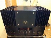
Pictures are of the 'current limit oscillation' into 4ohm load (5V/div), and the amp connected up for a test in the garage.
Everything tested without C101 and C143. I have now soldered those in, connected the power LED's at the front of the case, and mounted everything together. Will see how long it takes before I have some reason to get in there again to play around with something, it usually doesn't take long 🙂
After some experimentation/sims I have also added another 4,7uF(what I had at the moment) in parallel with the input cap, C111=470uF, 220u in parallel with C124, R123=470k. I'm a fan of a lot of capacitance. Anywhere I see phase diverging from 0deg before 20Hz in the sim, I try to add capacitance, just a thing 🙂
Pictures are of the 'current limit oscillation' into 4ohm load (5V/div), and the amp connected up for a test in the garage.
Attachments
I did some 1kHz square wave testing on the amp today, and it looked good as long as the load was 8ohm, some (damped) oscillations on the negative flank when it got current limited.
A previous builder discovered some problems with the AN 8R build when using 4ohm spkrs - iow, if your spkrs drop to 4ohms ... build the AN 4R (like I've done 🙂 ).
After some experimentation/sims I have also added another 4,7uF(what I had at the moment) in parallel with the input cap, C111=470uF, 220u in parallel with C124, R123=470k. I'm a fan of a lot of capacitance.
You've confused me with the above sentence?? Surely,
- the 'input cap' is C101 - which is given as 220pF on the "as built" 8R schematic.
- and C111 is given as 100uF on the "as built" 8R schematic.
- likewise, R123 is 330k on the "as built" 8R schematic.
Andy
In all schematics authored by Hugh, input cap is C1, and it's 10 uF.
220pF is a cap that goes from input to the ground.
220pF is a cap that goes from input to the ground.
In all schematics authored by Hugh, input cap is C1, and it's 10 uF.
220pF is a cap that goes from input to the ground.
Unfortunately, Hugh's numbering does not match up with the numbering used on the PCB - which is what counts! 🙂
But, yes ... my mistake, minek. The "input cap" is what is in series at the input - so C102/C104/C105 on the PCB and the 'as built' schematic. So 10uF.
Andy
As I see it, I used Hugh's recipe, and added a lite bit of pepper, and a bit less salt per my own taste 🙂 If I had something suitable in my boxes, I would even have gone for 20uF on the input cap.
The 4ohm test was just to see what happens when the amp is operating outside it's comfort zone, same as the cap parallel to load.
The 4ohm test was just to see what happens when the amp is operating outside it's comfort zone, same as the cap parallel to load.
As I see it, I used Hugh's recipe, and added a lite bit of pepper, and a bit less salt per my own taste 🙂 If I had something suitable in my boxes, I would even have gone for 20uF on the input cap.
The 4ohm test was just to see what happens when the amp is operating outside it's comfort zone, same as the cap parallel to load.
You have more knowledge about these things than I do, Rf. 👍
I can merely follow the recipe the chef has produced. 🙂
Andy
Last edited:
Don't worry, he's a good chef! 🙂
Indeed - I'm very happy with the sound of my AN 4Rs! 👍
(Much better-sounding than the previous amps of Hugh's that I've owned. 🙂 )
Andy
Fet amps are new to me, so I was looking at the datasheets for the output fets, and it seems the FQA's (that I'm using) have significantly higher capacitance than the IRFP's.
Input C: 3100pF vs 1300pF
Output C: 620pF vs 400pF
Not sure which is most significant though?
I'm thinking this could have some effect on the distortion rise at HF? Has anybody tried/measured both? I guess if it has been measured, it would most likely have been measured by XRK, but anybody is welcome to answer 🙂
I only tried IRFP's in the sim, and depending on the IRFP models used (have two) distortion varies significantly. It seems to be related to gate current, which I assume is dominated by capacitance. One of the models gives pretty nasty gate currents when output voltage is getting close to the rails.
Maybe the capacitance would also effects the harmonic profile to some degree?
Please consider I'm trying to learn here 😉
I actually like the sound of the FQA’s better. I don’t think the higher capacitance is an issue here. The FQA’s are also more thermally robust.
RF,
The input capacitance can be broken down to gate to source, and gate to drain. Since mosfets in output stages are used in source follower, the actual voltage change during operation from gate to source is minimal, particularly if gm is more than about 25, like the FQA Fairchilds. Effective GS cap is bootstrapped, so that aspect is not too important, particularly in a Class A where no outputs turn off. The important capacitance is gate to drain, because that varies as the output rises and falls. So the majority capacitance as a source follower is gate drain, and on the nmos FQA it is about a quarter (this varies as it's non-linear) of the Ciss, the total figure given of 3100pF.
Given that the two mosfets are always on, there is no migration of charge into and out of the gate, so used as a source follower, the rough figure of 800pF Cgd is not too important for audio.
These issues are incredibly important at high frequencies, and in Class AB amplifiers.
Hugh
Thank you for the education Hugh! 🙂 Thermal robustness was the reason I got them too, and later started thinking what else differs.
- Home
- Amplifiers
- Solid State
- Alpha Nirvana 39w 8ohm Class A Amp