Probably not the end of the world X. Can it still fit UMS format? I think that's the more important part.
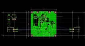
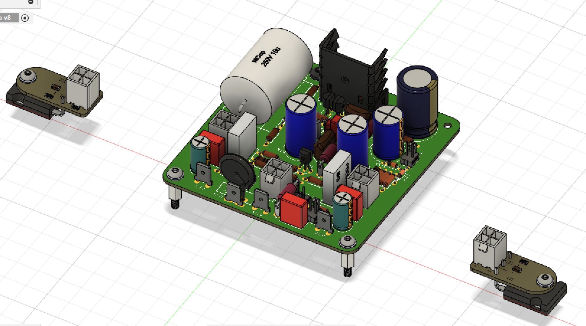
Yes, we will try - let me see if something like this can work - but necessitates a 5U Deluxe 400mm deep chassis. The existing UMS holes are too close to the bottom and lack two key locations for an idead dual high output MOSFET configuration - so maybe the standoffs fit UMS for the PCB proper, but we are probably going with Molex minifit Jr and flying leads for the MOSFETs to be located in ideal thermal locations. PCB is only 90mm x 90mm.
UMS compatible PCB standoffs:
Flying leads for MOSFETs:
Attachments
Last edited:
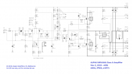
This looks great, Hugh. Looks like belts and suspenders are in place to handle any oscillation that may come along. The 2N5401 will be replaced by KSA992. There are some Fairchild output options (FQA40N25/FQA36P15) with higher thermal ratings that may require the drain to gate snubbers, but the option is therein any case. Nice to have clip indicator - a Class A amp meant to be used well above the First Watt!
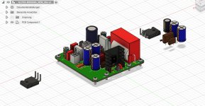
More progress on the Alpha Nirvana layout by JPS64. Looking really good.

Attachments
Last edited:
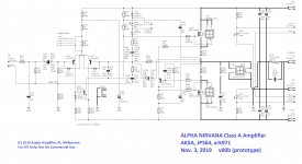
ALPHA 39W Class A Nirvana version
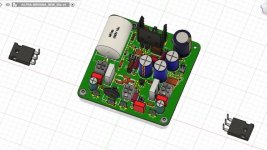
Latest corrections to the pcb, hopefully final.
With 90W total dissipation and 39W output at 50Vpp just under clip, this is a 43% highly efficient Class A with all the beauty of Class A sound. There are many protective diodes and caps around this circuit so it should be extremely robust and reliable. With a larger cooling pad on a CPU tower, you can fit two TO3-P devices alongside and so only two of these towers are needed for stereo. This makes this minimalist, cheap and easy to make and very compact.
HD
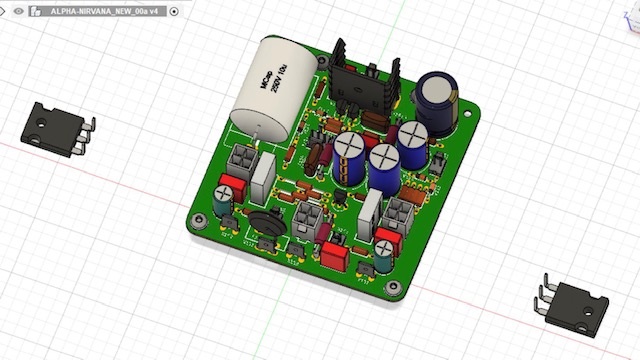
Attachments
You mean effect of absolute phase?
Given even order harmonics, you have asymmetry. If the transducer also presents any asymmetry, the effects may add or subtract depending on polarity.
The whole positive vs negative phase asymmetry. But for transient perfect speakers it’s important to be absolute phase time accurate in order to reproduce percussions correctly.
...it’s important to be absolute phase time accurate...
If the source was recorded w absolute phase inmind in the 1st place, and then given many one way and the others the other way you have to have a switch somewhere and mark every piece of sw as to which way the phase should be.
There is no set it once & leave it there if you are trying to preserve absolute phase.
dave
You literally would have to check the signal with an O-scope for a rim shot or kick drum to make sure the signal is a rising edge corresponding to compression wave.
Member
Joined 2009
Paid Member
I remember buying my first hi-fi in Canada and was surprised when the shop guy swapped around the speaker connections when he realized they were phase backwards that I could clearly hear an improvement. Since then I’ve always assumed we are phase sensitive.
You literally would have to check the signal with an O-scope for a rim shot or kick drum to make sure the signal is a rising edge corresponding to compression wave.
A well trained ear can pick it out pretty easy too.
And checking for a rim shot only ensures that drum is in absolute phase. What about the rest of the drum kit (say a mic on each) and all the rest of the ensemble?
dave
Member
Joined 2009
Paid Member
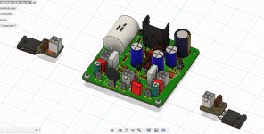
More progress. JPS64 is making some new helper PCBs for the MOSFETs with built in snubbers and the gate stopper resistor. Shown are SMT chip resistors but we are changing to carbon film MELF for their superior high pulse current absorption. The helper PCB also doubles as the large washer to clamp the MOSFET to a heatsink. Although this would not be needed if using a CPU cooler.
In which case, one could use an alternate format with no tab or a longer tab to clear the interference with the top mounted SMTs.
In which case, one could use an alternate format with no tab or a longer tab to clear the interference with the top mounted SMTs.
Attachments
Last edited:
We have never used gate protection diodes on the other Alpha amps and have not run into any issues. Having the snubbers and gate stoppers near the MOSFET legs is important though.
- Home
- Amplifiers
- Solid State
- Alpha Nirvana 39w 8ohm Class A Amp