I think slight asymmetries in the circuit are result of a lot of fine tweaking to ensure that the dominant harmonic distortion is not odd (3, 5, 7, etc) ordered. Perfectly balanced will usually result in lower overall THD at the expense of elimination of even order distortion. This would result in a harsher and more fatiguing sound. It’s very subjective of course, but these are what I refer to earlier as the “Aksa-approved” harmonic distortion profile.
It doesn’t get any simpler than 6 actives for this category of amp does it?
Why SE Class A and not PP? Again, SE Class A tends to have a more natural sounding harmonic distortion profile (dominant H2) vs PP which tends to have dominant H3.
X,
Exactly, perfectly balanced H2/H3 to my ears is pretty hideous!This is the salient point in audio for most people, whether they realize it or not.
As usual, thank you for all of your hard work!
Cheers,
Greg
.....I am thinking of keeping it close to the original Alpha 20 PCB board footprint and UMS compatibility. Maybe add some Molex connectors to allow for flying lead mounting of the MOSFETs.
Hi X,
Yes, please include the option of remote mounting with using the vertical mount Molex Minifit’s. Probably include a set of the P-mos/N-mos mini mounting pcb’s with onboard snubber also.
Thanks
Some predictions of the harmonic distortion profile in LTSpice at various power levels.
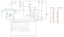
I have added an RFI filter to the input and this dropped the gain a bit to 27.0dB. I am using models for the KSA992, and also replaced Q4 with a KSA1381 (or TTA004) to provide room for a heatsink in case it gets too hot.
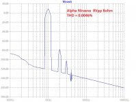
The FFT for 8Vpp into 8ohms looks like this:
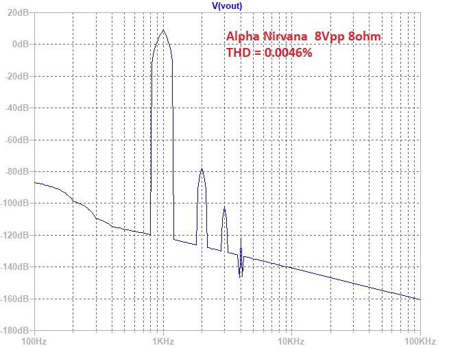
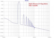
And at 27.2Vpp into 8ohms (12W), the FFT looks like this:
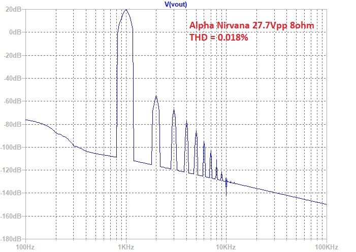
I think Hugh may be making some last minute tweaks to the circuit, so I won't post any updated schematics until then.
Code:
Here is 8Vpp or 1W into 8ohms:
Harmonic	Frequency	 Fourier 	Normalized	 Phase  	Normalized
 Number 	  [Hz]   	Component	 Component	[degree]	Phase [deg]
    1   	1.000e+03	4.001e+00	1.000e+00	   -0.87°	    0.00°
    2   	2.000e+03	1.848e-04	4.619e-05	 -117.68°	 -116.81°
    3   	3.000e+03	1.053e-05	2.631e-06	   58.71°	   59.58°
    4   	4.000e+03	2.313e-07	5.781e-08	  104.21°	  105.08°
    5   	5.000e+03	7.156e-07	1.789e-07	 -175.07°	 -174.20°
    6   	6.000e+03	5.836e-07	1.459e-07	  178.69°	  179.56°
    7   	7.000e+03	4.936e-07	1.234e-07	  178.79°	  179.66°
    8   	8.000e+03	4.319e-07	1.079e-07	  179.01°	  179.88°
    9   	9.000e+03	3.839e-07	9.596e-08	  179.12°	  179.99°
   10   	1.000e+04	3.455e-07	8.636e-08	  179.21°	  180.08°
   11   	1.100e+04	3.141e-07	7.850e-08	  179.28°	  180.15°
   12   	1.200e+04	2.879e-07	7.196e-08	  179.34°	  180.21°
   13   	1.300e+04	2.658e-07	6.642e-08	  179.39°	  180.26°
   14   	1.400e+04	2.468e-07	6.167e-08	  179.43°	  180.30°
   15   	1.500e+04	2.303e-07	5.756e-08	  179.47°	  180.34°
Total Harmonic Distortion: 0.004626%(0.004808%)

Here is 27.2Vpp or 12W into 8ohms:
Harmonic	Frequency	 Fourier 	Normalized	 Phase  	Normalized
 Number 	  [Hz]   	Component	 Component	[degree]	Phase [deg]
    1   	1.000e+03	1.387e+01	1.000e+00	   -0.87°	    0.00°
    2   	2.000e+03	2.483e-03	1.791e-04	 -121.70°	 -120.83°
    3   	3.000e+03	6.206e-04	4.475e-05	   59.08°	   59.96°
    4   	4.000e+03	1.880e-04	1.356e-05	    9.49°	   10.36°
    5   	5.000e+03	7.426e-05	5.355e-06	 -104.64°	 -103.77°
    6   	6.000e+03	2.763e-05	1.992e-06	  177.05°	  177.92°
    7   	7.000e+03	9.412e-06	6.786e-07	   89.53°	   90.40°
    8   	8.000e+03	1.830e-06	1.319e-07	  -14.32°	  -13.45°
    9   	9.000e+03	1.956e-06	1.411e-07	 -144.36°	 -143.49°
   10   	1.000e+04	1.602e-06	1.155e-07	  176.37°	  177.25°
   11   	1.100e+04	1.070e-06	7.715e-08	  172.05°	  172.93°
   12   	1.200e+04	9.599e-07	6.922e-08	 -179.95°	 -179.08°
   13   	1.300e+04	9.312e-07	6.714e-08	 -179.74°	 -178.86°
   14   	1.400e+04	8.648e-07	6.236e-08	  179.34°	  180.22°
   15   	1.500e+04	8.025e-07	5.786e-08	  179.38°	  180.25°
Total Harmonic Distortion: 0.018517%(0.018564%)

Here is 50Vpp (just before clipping) or 39W into 8ohms:
Harmonic	Frequency	 Fourier 	Normalized	 Phase  	Normalized
 Number 	  [Hz]   	Component	 Component	[degree]	Phase [deg]
    1   	1.000e+03	2.496e+01	1.000e+00	   -0.89°	    0.00°
    2   	2.000e+03	1.405e-02	5.630e-04	 -158.12°	 -157.23°
    3   	3.000e+03	1.391e-02	5.574e-04	   56.44°	   57.33°
    4   	4.000e+03	8.589e-03	3.441e-04	  -21.73°	  -20.84°
    5   	5.000e+03	6.813e-03	2.729e-04	 -135.45°	 -134.56°
    6   	6.000e+03	3.939e-03	1.578e-04	  118.95°	  119.84°
    7   	7.000e+03	3.691e-03	1.479e-04	    3.52°	    4.41°
    8   	8.000e+03	3.049e-03	1.222e-04	 -101.34°	 -100.46°
    9   	9.000e+03	3.149e-03	1.261e-04	  169.39°	  170.28°
   10   	1.000e+04	2.769e-03	1.109e-04	   84.89°	   85.78°
   11   	1.100e+04	2.897e-03	1.161e-04	    5.17°	    6.06°
   12   	1.200e+04	2.717e-03	1.088e-04	  -77.65°	  -76.76°
   13   	1.300e+04	2.811e-03	1.126e-04	 -163.48°	 -162.59°
   14   	1.400e+04	2.513e-03	1.007e-04	  107.42°	  108.31°
   15   	1.500e+04	2.402e-03	9.623e-05	   16.13°	   17.02°
Total Harmonic Distortion: 0.098380%(0.099638%)
I have added an RFI filter to the input and this dropped the gain a bit to 27.0dB. I am using models for the KSA992, and also replaced Q4 with a KSA1381 (or TTA004) to provide room for a heatsink in case it gets too hot.
The FFT for 8Vpp into 8ohms looks like this:
And at 27.2Vpp into 8ohms (12W), the FFT looks like this:
I think Hugh may be making some last minute tweaks to the circuit, so I won't post any updated schematics until then.
Attachments
With Tina , it is possible to start the distortion measurement after an adjusted delay because the beginning of the burst there is the transient function . To know the measurement is the steady state distortion the phase shifts should be 180° for the pair harmonics and on phase for odd ones . Your measurements are wrong , at 13Vp or 10W , Tina after 10ms delay measures 0.012% lower than yours , look at post 16.
Last edited:
With my modifications it goes down to 0.009%. By replacing the inputs Q1, Q2 with bc337 , it goes down to 0.007%.
Last edited:
Hey X,
Nice to see more diy stuff from Hugh, but why Audio Nirvana. That is a speaker brand.
And isn’t the theoretical maximum efficiency of a Class A amp 25%?
dave
Nice to see more diy stuff from Hugh, but why Audio Nirvana. That is a speaker brand.
And isn’t the theoretical maximum efficiency of a Class A amp 25%?
dave
Alpha Nirvana, not Audio Nirvana.
SE Class A can be higher efficiency if there a reactive “push-pull” provided by either an active CCS, as is the case here, or for example, by an inductor like in the MoFo.
SE Class A can be higher efficiency if there a reactive “push-pull” provided by either an active CCS, as is the case here, or for example, by an inductor like in the MoFo.
Alpha Nirvana, not Audio Nirvana.
Still confusing.
dave
Never made the connection between the two Dave... anybody else?
"Alpha Nirvana" has not been claimed or registered as a TM. But that is neither here nor there. Certainly Alpha and Audio do not remotely sound alike.
R7 plays important roll in trade off ,speed vs distortion . I adjust it for optimum speed to get 0.0055% Dtot. There is still margin in NFB as the sensitivity is high, but I will leave it to the spec of the designer. Tina doesn't have the bc327/40 model , with, it will still be better.
Attachments
To my knowledge, Hugh has used "Nirvana" to identify upgrade kits for his commercial products since the original AKSA 55. This is nothing new in the commercial AKSA scheme of naming things, at least.Still confusing.
The "Audio Nirvana" company just seem to market their own tube amps and a class D amp, their own speaker drivers, box plans and a powered subwoofer box, direct from St Louis. I wouldn't expect to see much confusion arising on this forum, at least.
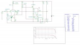
This is 4 ohms version . It has 0.0047% at 10w and 0.1% at 39w . The MOSFETs dissipate each 43.9w.THD to dB - convert percent % to decibels dB percentage voltage % vs per cent converter THD+N total harmonic distortions calculation signal distortion factor attenuation in dB to distortion factor k in percent decibel damping - sengpielaudio Sengpiel
0.019% THD -> -74.4 dB
BTW, how much power at 4 Ohms?
:
Attachments
Member
Joined 2009
Paid Member
Alpha Nirvana, not Audio Nirvana.
SE Class A can be higher efficiency if there a reactive “push-pull” provided by either an active CCS, as is the case here, or for example, by an inductor like in the MoFo.
I'm no expert, but my guess is that with global negative feedback the output is 'voltage output push pull' - if you want reactive inductor or current source behaviour you need to remove the global negative feedback. This amp uses a CCS yes, in a SRPP type of topology (it's been used before as an alternative to the Aleph current source) but the speaker will 'see' an amplifier with low output impedance dominated by the behaviour of the feedback loop.
All correct, Bigun........
One thing; the active CCS is concertina, the voltage across the two sources resistors will remain constant at 0.65V, but the two resistors will pass conjugate currents which will always sum to 3.4A. The two resistors are identical so that the see-saw action is completely symmetrical.
HD
One thing; the active CCS is concertina, the voltage across the two sources resistors will remain constant at 0.65V, but the two resistors will pass conjugate currents which will always sum to 3.4A. The two resistors are identical so that the see-saw action is completely symmetrical.
HD
Last edited:
Never made the connection between the two Dave... anybody else?
I thot about that, and it is the Nirvana part that bugs me, The speaker company ruined the use of the name Nirvana — so far i have heard no ANs that weren’t bad except one, and it was too pricey, so so far i have mixed views on them.
dave
Yes, but their TM filing specifically is for the combination “Audio Nirvana” together, the “Nirvana” by itself is too broad. It would be like trademarking the word “Great” or “Enlightenment”.
So, the word Nirvana in general needs to be used in combination with something else.
So, the word Nirvana in general needs to be used in combination with something else.
- Home
- Amplifiers
- Solid State
- Alpha Nirvana 39w 8ohm Class A Amp
