I think make numcycle=100 and that should do it but it’s aggravating to wait that long.
Btw, Panasonic ERX 3w resistors have tinned solid copper leads. They are pretty much the best power resistors for power amps.
Btw, Panasonic ERX 3w resistors have tinned solid copper leads. They are pretty much the best power resistors for power amps.
gate stoppers
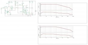
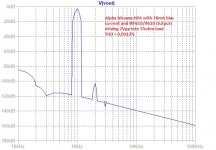
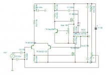
You have applied 100 ohms resistors on the gates , I suppose by tradition . R12 is strictly to decorate* the PCB , whereas R16 decreases the pole created by R15 and reverse capacitance of Q4 . Eliminating both you just get the effect of R15 by increasing the parasite pole higher . See the graphs and distortion ,measured in open loop without compensation capacitors.
* 120 ohm carbon 5% is more beautiful.
Attachments
If the circuit is oscillating and have poor bass , you know now where to look at. Think a little bit why electrolytic, ceramic ,high quality capacitors have magnetic leads . Non inductive resistors for audio are not axial .I think make numcycle=100 and that should do it but it’s aggravating to wait that long.
Btw, Panasonic ERX 3w resistors have tinned solid copper leads. They are pretty much the best power resistors for power amps.
Last edited:
Why do you keep insisting that ERX source resistors have unwanted inductance and will cause oscillation in THIS design, and did you use Panasonic ERX? Have you already built it? Panasonic ERX 3w metal thin film resistors do not induce oscillation. If there is oscillation, it’s more likely fixed with a 220pF and 47R snubber between the gate and drain of the MOSFETs. Those were used in the Alpha BB and ABBB amps. We may just add SMT placeholders for a tiny 47R and small Wima 220p 1000v MKP next to the legs as insurance.
Last edited:
For more than two years I played with this type of output, but always on positive side which allows to use N mosfets as the cheap IRFZ44 . I also have it as real SRPP using depletion mosfet DN2540 in compound Darlington with 2sa1943 . I have it in single stage , 2 stages with single input , 2 stage with differential input , single stage cyclotron. In all cases it is a big problem to have the CCS very fast so that it keeps the current constant at high frequencies and have it stable . I told you this circuit runs at 10 MHz loop , so must deal with it as HF component and not audio .
You are totally unaware of wire thickness vs current it carries. Have a look at American Wire table and see what thickness is to apply for 3A peak if it is not near chassis , you will understand why the leads should be magnetic . Wiring ,PCB threads must comply with the table's recommendation , or else the low frequencies that carry higher currents evaporate.
You are totally unaware of wire thickness vs current it carries. Have a look at American Wire table and see what thickness is to apply for 3A peak if it is not near chassis , you will understand why the leads should be magnetic . Wiring ,PCB threads must comply with the table's recommendation , or else the low frequencies that carry higher currents evaporate.
Last edited:
Hi KK,
Pretty presumptuous of you...
The only resistor components that I have with magnetic leads are the no name cheap ones from AliExpress and eBay. All of the reputable high quality (RF capable) resistors from Dale, Panasonic, Vishay, Yageo, etc have copper leads. I see plenty of people using them in projects with RF and high frequencies.
The layout is designed by JPS64 (a professional with 30 years of experience making mission critical aerospace circuits and audio circuit layouts - more than anyone else I know - so he does indeed understand wire or trace thickness vs current requirements and low frequency vs high freq layout practices). JPS64’s signature designs use double conducting traces stitched with numerous vias - the approach has seemed to work pretty successfully to provide a low inductance, low impedance path for audio signals in numerous amp projects that have been presented here on DIYA.
We hear your concerns for oscillations - Hugh and I get that - and the CCS is bloody fast, actually picking the KSA992 slowed it down a bit vs the 2N5401. But we are familiar with oscillations, how to check for them, and how to deal with them. There are many many fine points on the design by Hugh that are there for an audio-based reason which may not be obvious.
We appreciate your suggestions, but the design choices here have all been carefully thought out. Let’s make the verification build and see if there are oscillation issues. Let’s see how it sounds. But I am pretty sure that this design is not the same exact design you have been working on for years.
Regards,
X
You are totally unaware of wire thickness vs current it carries. Have a look at American Wire table and see what thickness is to apply for 3A peak if it is not near chassis , you will understand why the leads should be magnetic .
Pretty presumptuous of you...
The only resistor components that I have with magnetic leads are the no name cheap ones from AliExpress and eBay. All of the reputable high quality (RF capable) resistors from Dale, Panasonic, Vishay, Yageo, etc have copper leads. I see plenty of people using them in projects with RF and high frequencies.
The layout is designed by JPS64 (a professional with 30 years of experience making mission critical aerospace circuits and audio circuit layouts - more than anyone else I know - so he does indeed understand wire or trace thickness vs current requirements and low frequency vs high freq layout practices). JPS64’s signature designs use double conducting traces stitched with numerous vias - the approach has seemed to work pretty successfully to provide a low inductance, low impedance path for audio signals in numerous amp projects that have been presented here on DIYA.
We hear your concerns for oscillations - Hugh and I get that - and the CCS is bloody fast, actually picking the KSA992 slowed it down a bit vs the 2N5401. But we are familiar with oscillations, how to check for them, and how to deal with them. There are many many fine points on the design by Hugh that are there for an audio-based reason which may not be obvious.
We appreciate your suggestions, but the design choices here have all been carefully thought out. Let’s make the verification build and see if there are oscillation issues. Let’s see how it sounds. But I am pretty sure that this design is not the same exact design you have been working on for years.
Regards,
X
Hugh has been doodling on LTSpice and he came up with something really extraordinary: a 43% efficient SE Class A amp that can drive 39w into an 8ohm load with the usual Aksa-approved harmonic profile and low phase shift.
You make very pretty things but that marketing stories you put in the text are not for diy audio forums... That mosfet ccs in not an "original Aksa design", you could find it in couple of threads years back... Also with your "Aksa Lender" mantra it's a plane Lander connection,. Btw you made a LOT nice project but this part is annoying...
Cheers. 😉
Last edited by a moderator:

Hi Bogdan,
My mistake then, if the use of a PNP with the P-channel and two source sense resistors is not “original”. I’ll revise the text accordingly but the moniker Aksa Lender seems to be pretty descriptive of the front end topology used by several projects now for almost 3 years. Maybe you can give me link to the “plane Lander” that you are referring to?
My mistake then, if the use of a PNP with the P-channel and two source sense resistors is not “original”. I’ll revise the text accordingly but the moniker Aksa Lender seems to be pretty descriptive of the front end topology used by several projects now for almost 3 years. Maybe you can give me link to the “plane Lander” that you are referring to?
Last edited:
Member
Joined 2009
Paid Member
If I remember correctly (?): The "AKSA Lender" topology is not exactly the same as the original Lender. In the AKSA version there is only one transistor operating as a differential to single ended amplifier but the original Lender used two transistors. What you see in the AKSA was actually pre-dated by ME, if you look at my TGM4 amplifier thread from many years ago. It's more than likely there is a version that predates me too, perhaps in another publication by Lender because just about ALL of these things we are doing are obvious to anybody skilled in the art !
It occurs to me that no-one owns any of this IP. No-one can claim that they owned these circuits and there are no patents. Even the Pass active Aleph CCS patent is expired, and so all we are doing here is applying some innovation and moving around known blocks to make a unique topology. Besides a cool circuit is not a brilliant product, that comes much later. We are chefs, and our ingredients are modern components and some fairly old schematic tricks well documented in the public domain.
KK, you have given us useful information..... there is a clear danger the see-saw CCS here may oscillate at 10MHz and we need to be careful with component, wire and layout. Thank you for this; more than this we do not need to accept your presumptive tone and believe that we are building 'your circuit'. Ridiculous and insulting. We hear your points, we thank you for them, and we will act with care, and since there is no money transferred, please leave it at that.
Bigun, I could say a lot to you about the way your examined my many commercial circuits and gave away more information that I would have liked to the public domain. Now it appears we are designing something that you designed before, and we are using the Lender name to apply something it is not. You infer that we may have copied something of yours; in truth we did not, but in any event even if we did it should not be an issue either way because you do not have a patent. I understand you are the CEO of a technical company with private IP so I am sure you know more than most of us that DIYaudio is a free source, for anyone, for any purpose, and free of legal constraint in open source circuits.
Let's cool off here. This is just a schematic at present. It's not even in prototype. Already we have negative comments on its name, its design, and who said what and how in an insulting way...... be aware that you may be able to build this for yourself; nothing there to stop you. Pouring water on our attempts is hilarious, that is counter product and makes me think this could be actually pretty good. I'm getting more interested every day.....!
We need to build this thing, then listen to it with four or five good experienced listeners, and only then will this doodle on a napkin become a reality. Actually it's a refined, more efficient of the original ALPHA, which is a very, very good amp. In the meantime, accept that until this is done, and it's a known, real circuit, no-one will really know the truth and so all this negativity serves only to elevate a few tempers for no reason.
HD
Member
Joined 2009
Paid Member
I was responding to bogdan not you Hugh - pointing out all this rush to claim originality is nonesense!
Yes lots of enthusiasm for your amps - you were my inspiration for getting into this hobby in the first place with your AKSA amplifier ! I should be blaming you for thousands of hours spent hiding in my basement 😀
Yes lots of enthusiasm for your amps - you were my inspiration for getting into this hobby in the first place with your AKSA amplifier ! I should be blaming you for thousands of hours spent hiding in my basement 😀
Last edited:
My apologies. Since my incident about half of my speech area was wiped out and I find it difficult to read. Even writing is affected.......
I cannot accept your blame, Gareth, every young man has to have a hobby........
Hugh
I cannot accept your blame, Gareth, every young man has to have a hobby........
Hugh
Member
Joined 2009
Paid Member
unfortunately not so young anymore but the real pirates are outside today - it being Halloween there are kids everywhere !
Makes a great Preamp or Headphone Amp too
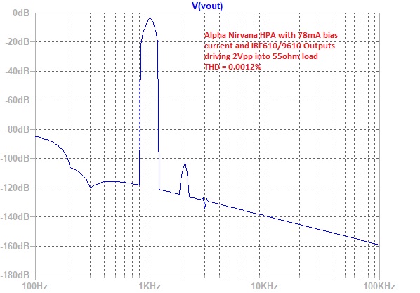
Just replace the outputs with IRF610 and IRF9610 and source resistors with 4.7ohm ea. This gives 78mA bias current.
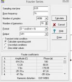
Here is FFT for 2Vpp into 55ohms, THD is 0.0012%:
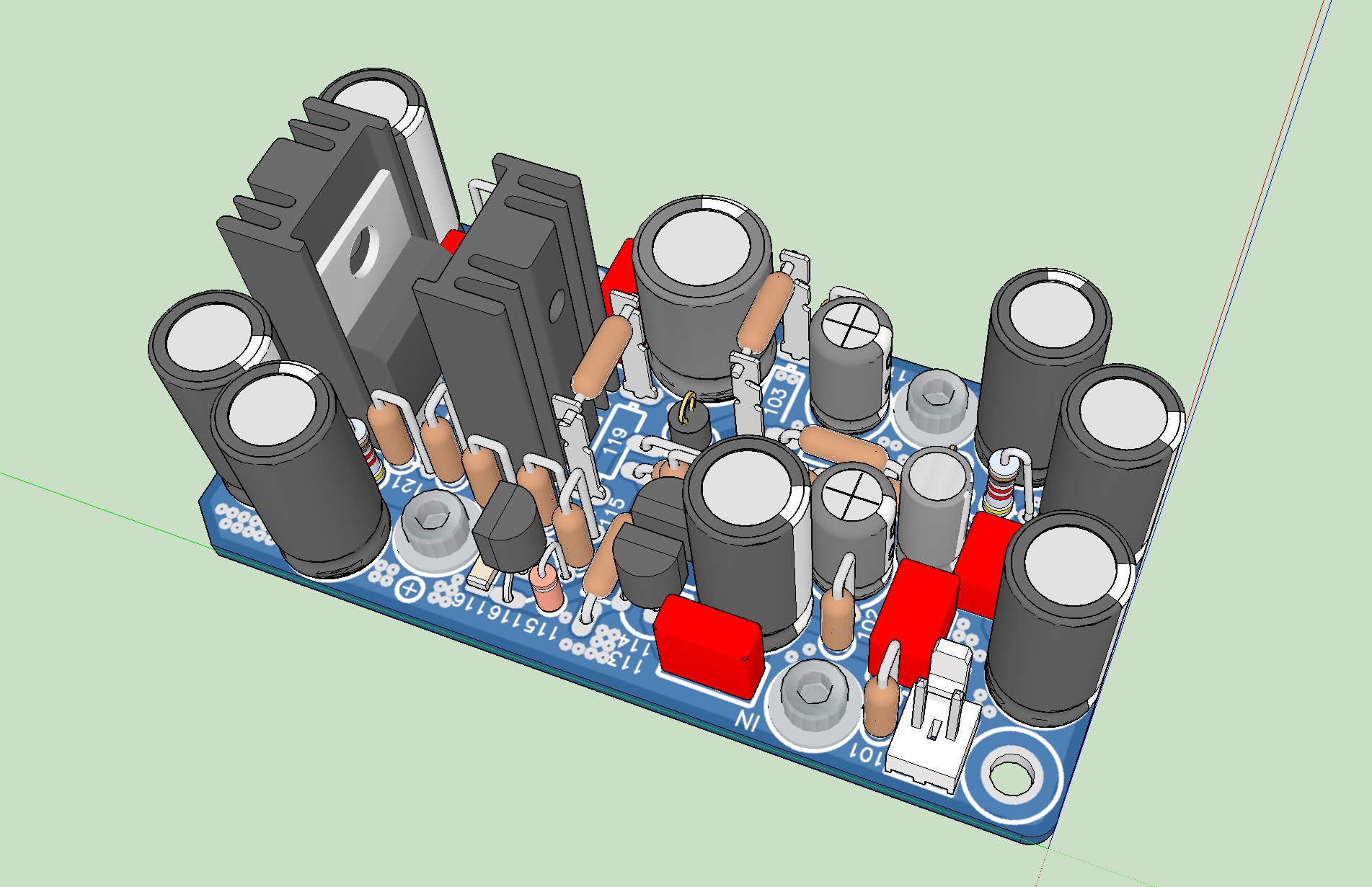
This could all be stuffed onto the usual Yarra daughterboard format. Sort of looks like the Melbourne actually:
Just replace the outputs with IRF610 and IRF9610 and source resistors with 4.7ohm ea. This gives 78mA bias current.
Here is FFT for 2Vpp into 55ohms, THD is 0.0012%:
This could all be stuffed onto the usual Yarra daughterboard format. Sort of looks like the Melbourne actually:
Attachments
Aksa ,If you read again , I said the principal of this circuit is same described in CCPP . My nearest circuit resemble yours is shown bellow . As Begun said it is a variant of SRPP . If I show you this because it rich with experience. First the bias is not as your sim can show . The sense resistors are 5% each , this gives +/- 10% variation on 1.8A . If you look on Telefunken datasheets for IC/Vbe variations by manufacturing for BD139 or BC327, the unlucky DIY can end up with 2.1A or 1.5A bias . In the circuit if I use BD139 (Ft=55Mhz) instead of 2SC3597 (Ft=800Mhz) which was the initial choice , the sound of the amplifier becomes ultra comfortable to listen . The higher I was pulling the volume the more was requesting my unquenchable ears , until the neighborhood alerting me to be excessive. Yes , I don't feel the sense of loudness as the transients are blunted but it is great sounding to cover a noisy environment with more agreeable . The upper circuit can also be realized by DN2540 in compound Darlington with 2SA1943. It doesn't require bootstrap the base emitter resistor 10 ohms and two sense resistors 0.5 ohm each resulting superior quality . If I only posted the CCPP because in all other configurations I was lacking in bass performance , when I got the perfection I was expecting with CCPP , all others went forgotten. I have great impression your amp will also suffer of lack of bass , unless 3 stage configuration that I never tried makes miracles.
Now that I have superior sound character with class AA that generates odd order harmonics of opposite phase to subtract with that of the speaker's and higher the dynamics , SRPP circuits , as class A ,belongs to the my past .
Now that I have superior sound character with class AA that generates odd order harmonics of opposite phase to subtract with that of the speaker's and higher the dynamics , SRPP circuits , as class A ,belongs to the my past .
Attachments
Last edited:
Many thanks, KK, it appears a slow control CCS transistor is better rather than a fast one; a good example would be an A992 which is around 50MHz min, similar to the BD140 you used. I will also use a 100pF from base CCS to gate pmos, and I have noticed considerable oscillation around 3MHz coming off negative peak without it.
We hear you, and offer thanks for your good advice. There is another variant of this active CCS I am considering too.
Please watch this thread for changes.... my thanks,
Hugh
We hear you, and offer thanks for your good advice. There is another variant of this active CCS I am considering too.
Please watch this thread for changes.... my thanks,
Hugh
The 3Mhz is due to 1k R15. Try with 100 ohms but reduce the gain by decreasing the current by R18 to be 22k. Now all by listening, you can Tune the sound by R8 and R18.
It looks like Alpha Nirvana won’t be a 1:1 drop in footprint with Alpha 20. The thermal requirements dictate more spacing between the MOSFETs. We tried but doesn’t work.
It looks like Alpha Nirvana won’t be a 1:1 drop in footprint with Alpha 20. The thermal requirements dictate more spacing between the MOSFETs. We tried but doesn’t work.
Probably not the end of the world X. Can it still fit UMS format? I think that's the more important part.
- Home
- Amplifiers
- Solid State
- Alpha Nirvana 39w 8ohm Class A Amp