Just one question, does the mosfets need gate protection diodes ?
If your soldering iron is not earthen or worse ordinary high voltage non isolated, you have great chance to destroy gate-source isolation . Apply between gate and source at the root of the feet any zener 1/2w 5.6v-20v , solder it with soldering iron unplugged . When all finished it cutoff , but leaving it on can protect from future soldering intervention .
Last edited:
Thanks guy's, it is just that almost all vertical fet outputs make use of the gate protection diodes and the lateral fets has them build in already.🙂
IRFP240/9240 are not protected. Even so the high voltage soldering iron can even destroy the diode .Thanks guy's, it is just that almost all vertical fet outputs make use of the gate protection diodes and the lateral fets has them build in already.🙂
We are adding gate protection Zener to circuit. Probably will go on the small helper PCB attached to MOSFET.
Ready for making PCBs, finally
I want to thank JPS64 for another amazing layout and for his patience in working with me and Hugh, we kept coming up with changes every day. But JPS64 never complains - instead, he says he likes challenges!
Thank you, JPS64!
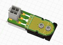
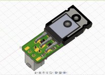
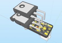
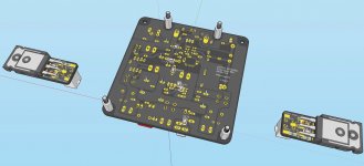
Here are the fine details of the little helper PCBs that connect the MOSFETs to the main board and provide the important job of snubbing, gate stopping, and Zener protection. Because of all of these functions packed into a small space, and the desire to get them as close to the pins as possible, we had to go with SMT here. So just a few easy to solder SMT parts. The helper PCBs also serve as a clamp washer for the MOSFETs (choice of either TO-247 or TO-264) if using with a conventional heatsink - or a clamp bar spacer of using with CPU cooler. Hence they have lots of thermally conductive vias. Use of Molex Minifit Jr connectors are optional - straight flying lead soldered joints are also possible.
I want to thank JPS64 for another amazing layout and for his patience in working with me and Hugh, we kept coming up with changes every day. But JPS64 never complains - instead, he says he likes challenges!
Thank you, JPS64!
Here are the fine details of the little helper PCBs that connect the MOSFETs to the main board and provide the important job of snubbing, gate stopping, and Zener protection. Because of all of these functions packed into a small space, and the desire to get them as close to the pins as possible, we had to go with SMT here. So just a few easy to solder SMT parts. The helper PCBs also serve as a clamp washer for the MOSFETs (choice of either TO-247 or TO-264) if using with a conventional heatsink - or a clamp bar spacer of using with CPU cooler. Hence they have lots of thermally conductive vias. Use of Molex Minifit Jr connectors are optional - straight flying lead soldered joints are also possible.
Attachments
Last edited:
xrk, Hugh and JPS, sorry for giving you guy's extra work and thanks for the hard work !!🙂
xrk, sorry one last request, can you plse update the schematic, no more extra work I promise !!
xrk, sorry one last request, can you plse update the schematic, no more extra work I promise !!
Last edited:
Nice work X, JP and Hugh 🙂
X, good move to keep the “helper pcb” SMT components out of the way of the clamping bar if mounting on a CPU cooler.
X, good move to keep the “helper pcb” SMT components out of the way of the clamping bar if mounting on a CPU cooler.
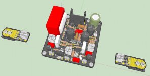
Thanks, Vunce. JP did all the work here - and he came up with a very elegant solution, and what I believe is a very handy tool for other amps, should anyone wish to free themselves of the need to connect an output MOSFET to the main PCB. By having the snubber, gate stopper, and protection diode all on the little local helper PCB, I think it really opens up a lot of opportunity for anyone wishing to move their MOSFETs off the main board and onto a non-conventional heatsink. I can think of a lot of options.
@Vrystaat: thanks for your suggestions - we aim to make a bullet-proof amp, ready to take on any potential oscillation. Will have to wait for JPS64 to send out the updated schematics with the new layout and post processed CAM files.
.....By having the snubber, gate stopper, and protection diode all on the little local helper PCB, I think it really opens up a lot of opportunity for anyone wishing to move their MOSFETs off the main board and onto a non-conventional heatsink. I can think of a lot of options.
Exactly!! 😉
Aksa ,If you read again , I said the principal of this circuit is same described in CCPP . My nearest circuit resemble yours is shown bellow . As Begun said it is a variant of SRPP . If I show you this because it rich with experience. First the bias is not as your sim can show . The sense resistors are 5% each , this gives +/- 10% variation on 1.8A . If you look on Telefunken datasheets for IC/Vbe variations by manufacturing for BD139 or BC327, the unlucky DIY can end up with 2.1A or 1.5A bias . In the circuit if I use BD139 (Ft=55Mhz) instead of 2SC3597 (Ft=800Mhz) which was the initial choice , the sound of the amplifier becomes ultra comfortable to listen . The higher I was pulling the volume the more was requesting my unquenchable ears , until the neighborhood alerting me to be excessive. Yes , I don't feel the sense of loudness as the transients are blunted but it is great sounding to cover a noisy environment with more agreeable . The upper circuit can also be realized by DN2540 in compound Darlington with 2SA1943. It doesn't require bootstrap the base emitter resistor 10 ohms and two sense resistors 0.5 ohm each resulting superior quality . If I only posted the CCPP because in all other configurations I was lacking in bass performance , when I got the perfection I was expecting with CCPP , all others went forgotten. I have great impression your amp will also suffer of lack of bass , unless 3 stage configuration that I never tried makes miracles.
Now that I have superior sound character with class AA that generates odd order harmonics of opposite phase to subtract with that of the speaker's and higher the dynamics , SRPP circuits , as class A ,belongs to the my past .
can the bc327 be replaced by bc550?
can the bc327 be replaced by bc550?
Yes, we have designed it for stability with a snubber on the CCS transistor and on the mosfet. I understand KK's comments earlier; this is one area in audio where the transistor should be SLOW, rather than a BC550 however. A BD140 is a good choice, as is a KSA992.
Beautiful pcb work from JPS..... this will be a killer amp!
Hugh
Thanks xrk, Hugh and JPS for amazing work done so far!
This project looks very professional, 39w class A from 27 volts, wow!
In anticipation, could you advise on the most suitable chassis from the DIY Audio store?
Will there be a pre amp module so I could build an integrated amplifier with input and volume controls?
Many thanks
Ian
This project looks very professional, 39w class A from 27 volts, wow!
In anticipation, could you advise on the most suitable chassis from the DIY Audio store?
Will there be a pre amp module so I could build an integrated amplifier with input and volume controls?
Many thanks
Ian
webby,
In the following post by Hugh, he recommends a minimum heat-sink (for one channel) with dimensions of 350mm x 150mm x 50mm with vertical fins.
https://www.diyaudio.com/forums/sol...nirvana-39w-8ohm-class-amp-2.html#post5958892
The Deluxe 5U chassis from the diyAudio store would cover that.
The Disspante 5U also looks ok, and even the 4U chassis just might be adequate too (but not sure).
Last edited:
I have the 4U x 300mm Dissipante and it’s good for about 75w. This one is 90w so probably should be 5U. However, a 120mm Noctua fan on each side could make the 4U or even 3U work well.
This amp will have about 28-29dB gain so technically could work without a preamp. It’s not like some other Class A amps that are only 15dB gain.
However, if you were looking for a preamp with a similar sound signature, the Yarra is the way to go. Use it with the Melbourne daughterboard.
The YARRA Preamplifier/HPA for Melbourne DB Group Buy
Simpler to make is the Aksa Lender preamp - single ended cap-coupled.
AKSA's Lender Preamp with 40Vpp Ouput GB
Last edited:
Verification PCBs just ordered
I double checked the Gerber files with a magnifying glass and all looks good. This is the first project that JPS64 is making on Fusion360 CAM processor so we are making extra sure things all look good. Also will only get a few boards to test in case they are duds. I am sure it wil work though!
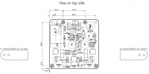
Here is the stuffing guide:

Placing the order makes it just that more real. Only 1.6mm HASL finish but 2oz copper in green solder mask to distinguish from production boards which will be blue.
I double checked the Gerber files with a magnifying glass and all looks good. This is the first project that JPS64 is making on Fusion360 CAM processor so we are making extra sure things all look good. Also will only get a few boards to test in case they are duds. I am sure it wil work though!
Here is the stuffing guide:
Placing the order makes it just that more real. Only 1.6mm HASL finish but 2oz copper in green solder mask to distinguish from production boards which will be blue.
Attachments
We are working on the BOM and Zman01 has helped by building a full featured Mouser shopping cart for “one-click” ordering. The good news is that it looks like the BOM from Mouser is coming up at around $55 per channel. That’s very good for a state of the art 39W Class A amp!
Thank you, Zman01 for helping us with the BOM shopping cart!
Thank you, Zman01 for helping us with the BOM shopping cart!
- Home
- Amplifiers
- Solid State
- Alpha Nirvana 39w 8ohm Class A Amp