Andy,
Nico is correct.
You can span a 100R pot across the two sensing resistors, and then take the wiper off to the base of the sensing transistor.
If you set a 1.7A quiescent with two 0.22R resistors, the wiper can then select from 1.7A to say up to 3.4A at half way on the pot.
You would use the existing 1k base stopper resistor run from the wiper.
In truth, you could use a 100R carbon pot because the current consumption of the base of the transistor is little more than 200uA.
HD
gents lets not pollute this great thread with nonsense
You haven't come across 'irony' before? 🙂
Andy,
Nico is correct.
You can span a 100R pot across the two sensing resistors, and then take the wiper off to the base of the sensing transistor.
If you set a 1.7A quiescent with two 0.22R resistors, the wiper can then select from 1.7A to say up to 3.4A at half way on the pot.
You would use the existing 1k base stopper resistor run from the wiper.
In truth, you could use a 100R carbon pot because the current consumption of the base of the transistor is little more than 200uA.
HD
Thanks, Hugh. 👍
Hugh (and others) a little off topic but relevant in some way and I have a fair grasp of electronics. Why does a class A amplifier sound louder than a class AB amplifier? And there is no pun attached to the question. I can listen to my JHL at much lower volume setting than a 100 watt class AB and hear everything far better on the same speakers, room and conditions. Does anyone think it could be the cross-over distortion playing a role.
If you look at the current swing in each output device although you cancel the cross-over with some conduction, both the output device are not linear at this point and you have to increase the volume level to overcome the deficiency. Anyone?

Huh, isn’t your question wrong formulated?
I think that right one would be “why class A amplifiers can be listened at lower levels than class AB while providing the same level of immersion in sound?”.
And, of course, before that there is a question of any study providing evidence that class A is perceived as louder than class AB. 🙂
I’ve found, more than once, someone switching to very low distortion loudspeakers, claiming that now he finds himself listening at lower sound levels than before. So, if there is such effect with class A, it could be related to distortion difference, especially at low levels.
I made some changes to the input wires ..double shielded and silver I think With a simple multimeter Rms the measured noise on the scale of millivolts Ac 0.200mv and the other channel 0.400mv ac The fan controller is powered from this channel. which meters noise of 0.400 ac mv All this with the input NOT short.
My bias is at 2.6A. 0.15Ω+1Ω parallel.
AMAZING AMP!!
My bias is at 2.6A. 0.15Ω+1Ω parallel.
AMAZING AMP!!
Attachments
Last edited:
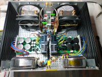
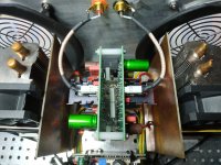
CPU coolers are a great way of getting rid of heat quickly. Well done/
Nico not only.It weighs much less, you can move it very easy , and the most important ha ha ha in the winter it will also serve as a heater. With the high price per kilowatt hour here in Greece the usage should be disappointing but the sound quality is very rewarding. 1 kwh = 0.15€ _ 0.20€ They have introduced the price of the kilowatt hour to the stock market and the Greeks They are saddened by this but they are not listened to...primarily the profits of private companies .CPU coolers are a great way of getting rid of heat quickly. Well done/
Last edited:
Thank you my friendGreat job Nikos!
I especially like the clean "stealthy" cpu cooler install.
Close the lid and the amp looks like a plain AB, not the Class A beast hidden within!
Enjoy your weekend!
I will do it I am looking for a wood front panel and perforated sheet metal with larger holes from this one at bottom.
Have a very nice weekend too
Hi, I just started testing the parts of my Alpha Nirvana 20w/8ohms. SFP soft star and SLB power supply are working properly. The transformer is a Toroidy 2x18v/400va.
These measurements are with a single AN channel.
The transformer output 19v/19v and the SLB output +/-23v (both should drop a little more when connecting both channels).
The voltage at R111 (1k75) is 4.6v set with potentiometer R113 (1K5) which set to 1K1 gives 2.6mA for the LTP stage. DC offset 19mv.
I have a question with the voltage measurement of the source resistors R141/R142 (0.27ohms). This voltage is 340mv and using the ohm's law:
I=V/R=0,340v/0,27ohms= 1,25A. Shouldn't this measurement be somewhat higher? Something like 1.65A/1.7A?
The truth is that looking at Mr. Hugh's simulation, the voltage of the source resistors is similar, slightly higher 354mv, so I=0.354v/0.27ohms= 1.3A.
Thank you in advance and best regards
The base bias of the sensing transistor V131 draws quite a bit of current which increase the required drive. In most cases R134 drops about 100mV so this requires more than the expected 0.65V across the combined sense resistors, R141/R142.
Hope this is clear; I am somewhat wooly headed this morning!
Hugh
Hope this is clear; I am somewhat wooly headed this morning!
Hugh
- Home
- Amplifiers
- Solid State
- Alpha Nirvana 39w 8ohm Class A Amp


