Daanve,
You love to find the cracks, don't you?
X DID indeed use 8R for the 53.4Vpp and this is {53.4exp2}/64=44.5W.
If you add the additional 1W used in the early stages and the bootstrap resistors, you have a total consumption of 95W, and for 44.5W out into 8R, we have an efficiency of 47.9%. The theoretical max is in fact 50%, so this is doing extremely well........
It is significant that this efficiency is only at full output, and only into an 8R resistive load, which is not realistic for a real world speaker. But it is a very high efficiency for a single ended push pull SS amplifier, particularly using mosfet outputs, which have very high Vgs bias.
HD
Hi Hugh,
Sorry I was not clear here - it was very late wee hours of the morning. I made the measurement at 10ohms, but here is the data for 8ohms. This is not a nice ultra-low inductance dummy load, but a conventional wire wound and potted in aluminum body dummy load 25w each wired series-parallel for 100w, but probably less since not mounted on a real heatsink.
At a bonafide 8ohm load, I was able to get 51.6vpp before clipping for 41.6wrms or 44% efficiency based on 94w thermal input. This matches nicely against the 43% predicted efficiency from LTSpice sims that you ran as mentioned on Post #1. I don't want to lead anyone on a technical fairytale. 😉
Attachments
Last edited:
I just checked the clip indicator LED to see if it corresponds to what I see on the O-scope. It is pretty neat but the clip indicator LED matches precisely what I picked for onset of clipping. The Alpha Nirvana clip indicator comes on at 18.11vrms for the left channel and 18.05vrms for the right channel. This corresponds to 41.0w on the left and 40.7w on the right channel. Totally forgot to look at it before (as it is on the PCB). Anyhow, just thought that I report that it works as designed.
Thanks for checking the clip indicator X.
Did you use two diodes or a red led, a 4148 and a 2.7V zener?
Nice to have a clip indicator in a Class A amp.
HD
Did you use two diodes or a red led, a 4148 and a 2.7V zener?
Nice to have a clip indicator in a Class A amp.
HD
If a chassis comes to fruition on this amp, then it would be very nice to have the clip indicator LED for each channel on the front panel. Those who build their own chassis could easily install the LEDs on the front and run a twisted pair back to the PCB where the LED's are currently.
Hi X and Hugh,
IMHO, the birth of the AN is a very interesting process of antipode collaboration between you guys. Thanks to your calm and always factual replies to a number of questions and remarks, I am learning quite a bit on this new topology.
Thanks,
Jacques
IMHO, the birth of the AN is a very interesting process of antipode collaboration between you guys. Thanks to your calm and always factual replies to a number of questions and remarks, I am learning quite a bit on this new topology.
Thanks,
Jacques
Thank you Jacques,
I enjoy the intellectual and companionable nature of this topic, and in fact I have sold many amps over the years into France....
Hugh
I enjoy the intellectual and companionable nature of this topic, and in fact I have sold many amps over the years into France....
Hugh
If a chassis comes to fruition on this amp, then it would be very nice to have the clip indicator LED for each channel on the front panel. Those who build their own chassis could easily install the LEDs on the front and run a twisted pair back to the PCB where the LED's are currently.
That’s the plan. The PCB actually has outlines for a 2pin Molex kk where LEDs are to allow remote LED indicator mounting. True for PSU rails indicator too.
@Hugh, I am using 2N4148/red LED/2.7vZ for clip.
X, you guys have all bases covered with these designs, again well done to all concerned - most impressive.
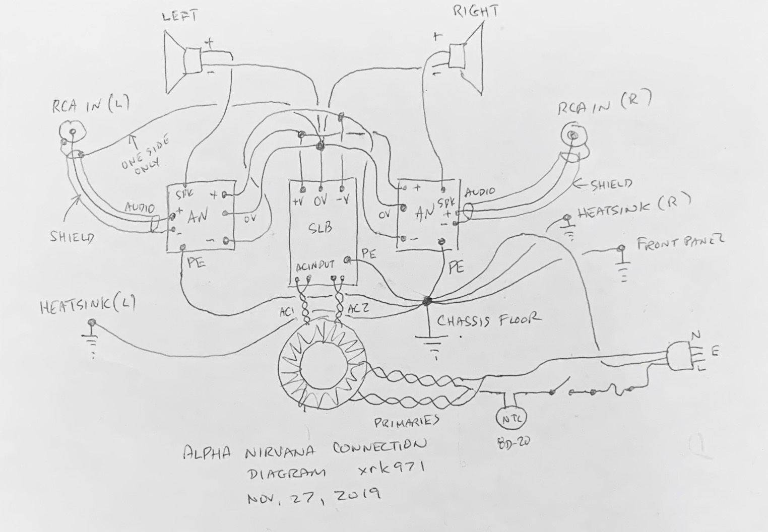
Here is how I connected the Alpha Nirvana with the SLB and my chassis. The one wire from RCA (L) ground to the star GND hub is optional. It reduced the amount of hum ever so slightly. The RCA ground is electrically isolated from the chassis panel via the shoulder washers that come with it.
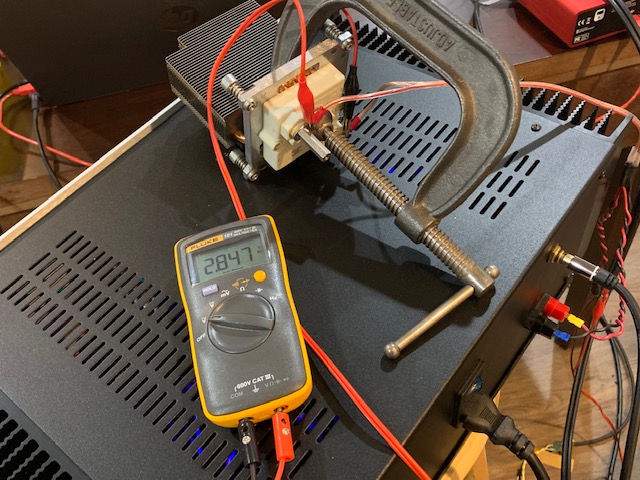
Here is the 300w 10ohm load resistor connected to a CPU cooler heatsink:
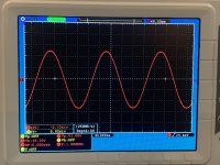
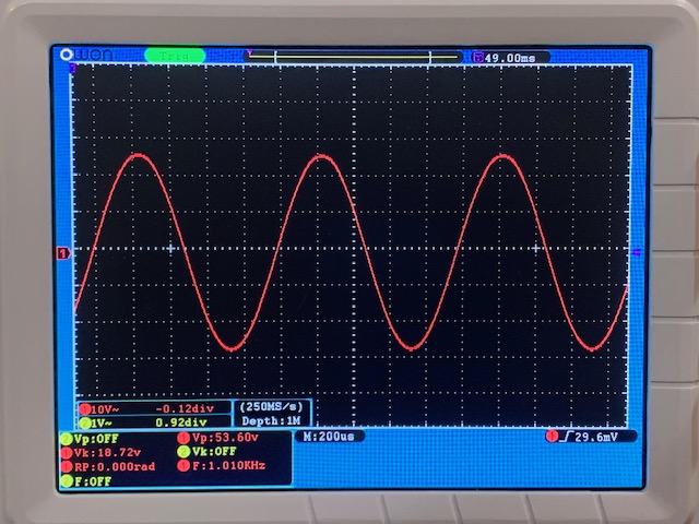
Here is clipping performance of this amp with a 300w 10ohm ultra-low inductance resistor. A nice symmetric and clean clip at 54.6vpp:
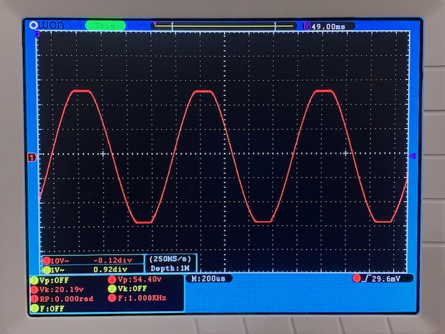
Here is the output just before the onset of clipping (53.4vpp) which would be about 46.5w into an 8ohm load:
46w from 94w thermal dissipation is 49% efficiency - very good for a SEPP amp.
Continuing to do more long term listening. The soundstage and imaging are excellent.
Very nice Class A amp guys well done!
Can I suggest one small mod to the chassis wiring?
Having designed and built a few class A amps I found that connecting the loudspeaker ground return directly at the amp module it self, in your case it would be amp module Power GND connection rather than directly connecting it to the power supply GND. if you try this I suspect your left channel input shield connection to PSU GND can be removed.
What this earthing topology will do is to provide a single GND return from the amp module back to PSU GND, rather than the two point return you have currently. 🙂
I hope this helps?
The one ground connection from the RCA to the PSU star hub probably should probably be removed. I will check it again - it was installed as a result of trial and error. In my experience, having the speaker return go straight back to the PSU Star GND hub makes for a quieter amp. It is an option on this board to return to the board as there is provision on the mini Quickfit connector for a speaker return. The user may try it either way and stick with whichever is quieter.
Thank you Anthony, good advice, particularly as grounding is an art form on audio amps. In efficient speakers, you can easily pick up just under 5mV hum and it drives builders crazy.
X, I always take speaker ground back to the center point earth between power connections and a 10R float for the input ground, fb shunt and input device bias resistor. It normally works but I have been disappointed more than a few times over the years. Still, it is the best option I've seen, so I invite any good ideas here!
HD
Thank you Anthony, good advice, particularly as grounding is an art form on audio amps. In efficient speakers, you can easily pick up just under 5mV hum and it drives builders crazy.
X, I always take speaker ground back to the center point earth between power connections and a 10R float for the input ground, fb shunt and input device bias resistor. It normally works but I have been disappointed more than a few times over the years. Still, it is the best option I've seen, so I invite any good ideas here!
HD
Yes I have used the 10R float on the Signal and feedback GNDs since the 1980s as well and for years use to connect the LS GND to the centre point of the power supply and for Class AB it worked just fine. But about a year a go I purchased a more expensive Audio analyers (AVERLAB) and discovered doing FFT tests that I could see a 50hz hump albeit down by -100db, I discovered that by moving the LS GND return as close as possible to the point where the 10R float resistor terminated at power GND on the amplifier module the 50hz hump dissappeared, with Class A amps where very high currents as high as 4 amps bias running around this became even more pronounced and the need to make this connection in this way was mandatory.
Any way just wanted to help and I hope this info can be of use. 🙂
Well X, with HD and Anthony chipping in advice on power supply grounding techniques, in the end, this should be one of the quietest amps around. Look forward to your comments after trialling what has been suggested by both experts.
I agree, troubleshooting ground loops is a black art by itself.
Thanks X for the grounding diagram, it helps new builders to get good results with less effort n time.
Looking forward to the GB.
Thanks X for the grounding diagram, it helps new builders to get good results with less effort n time.
Looking forward to the GB.
...But about a year a go I purchased a more expensive Audio analyers (AVERLAB) and discovered doing FFT tests that I could see a 50hz hump albeit down by -100db, I discovered that by moving the LS GND return as close as possible to the point where the 10R float resistor terminated at power GND on the amplifier module the 50hz hump dissappeared, with Class A amps where very high currents as high as 4 amps bias running around this became even more pronounced and the need to make this connection in this way was mandatory.
I take note. Thank you very much!
Yes I have used the 10R float on the Signal and feedback GNDs since the 1980s as well and for years use to connect the LS GND to the centre point of the power supply and for Class AB it worked just fine. But about a year a go I purchased a more expensive Audio analyers (AVERLAB) and discovered doing FFT tests that I could see a 50hz hump albeit down by -100db, I discovered that by moving the LS GND return as close as possible to the point where the 10R float resistor terminated at power GND on the amplifier module the 50hz hump dissappeared, with Class A amps where very high currents as high as 4 amps bias running around this became even more pronounced and the need to make this connection in this way was mandatory.
Any way just wanted to help and I hope this info can be of use. 🙂
Thank you for your advice. I hooked up my 10R 300w ultralow inductance dummy test load and then connected my Focusrite 2i4 to it with 10:1 balanced voltage divider (AC coupled via a pair of 1uF Wima MKS caps). Turned on REW in RTA mode and looked at the noise background FFT like a stethescope to do real-time grounding checks.
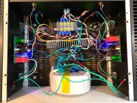
So I found that it helped to connect the return for the speaker back to the amp PCB as you suggested. This dropped the 60Hz mains peak by about 20dB - significant. But it is not zero. I also disconnected the funky gnd from the RCA -ve to the 0v hub. That helped by about another 5dB. The biggest difference was just moving the AC wire bundles around to tiy them up and keep them tightly coiled near the trafo. In fact, I stuffed the excess AC wires into the donut hole of the trafo and taped them shut with a piece of Kapton tape. That reduced a lot of the HF mains hash that I was seeing. I also added a ground wire from the SLB heatsink to the chassis ground. I added dediccated ground wires from each heatsink to the chassis gorund point. I think the remaining 60Hz peak and higher order mains harmonics are probably from EMI radiated from the trafo itself being in close proximity of the boards.
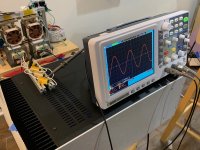
The amp now looks like this:
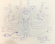
Here is the new grounding diagram v2:
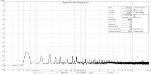
And here is the resulting background noise FFT for the Alpha Nirvana as connected above. With my ears pressed to the speaker cone, there is no noise. It is a very quiet amp now. The Fluke 101 measures 0.1mV rms noise with the sound source turned to zero volume.
Attachments
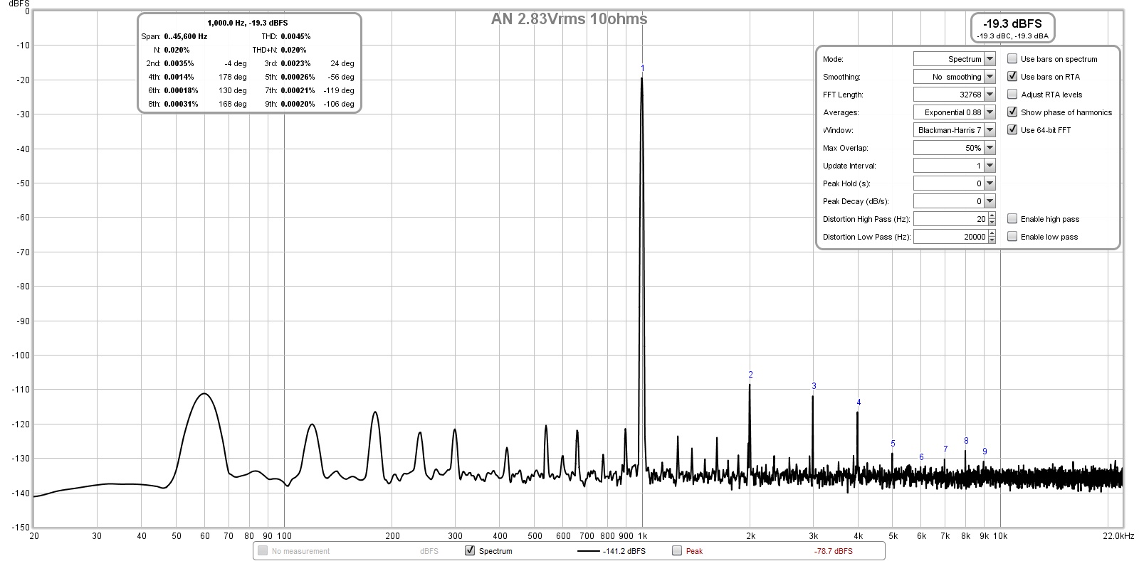
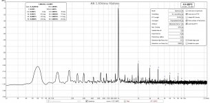
With the above setup connected and producing a fairly clean background, I proceeded to measured the distortion using the 10ohm ultra low inductance dummy load.
Here is the FFT for 2.83vrms into 10ohms (800mW) for 0.0045% THD:
This is for 3.16vrms into 10ohms (1w) for 0.0048% THD:

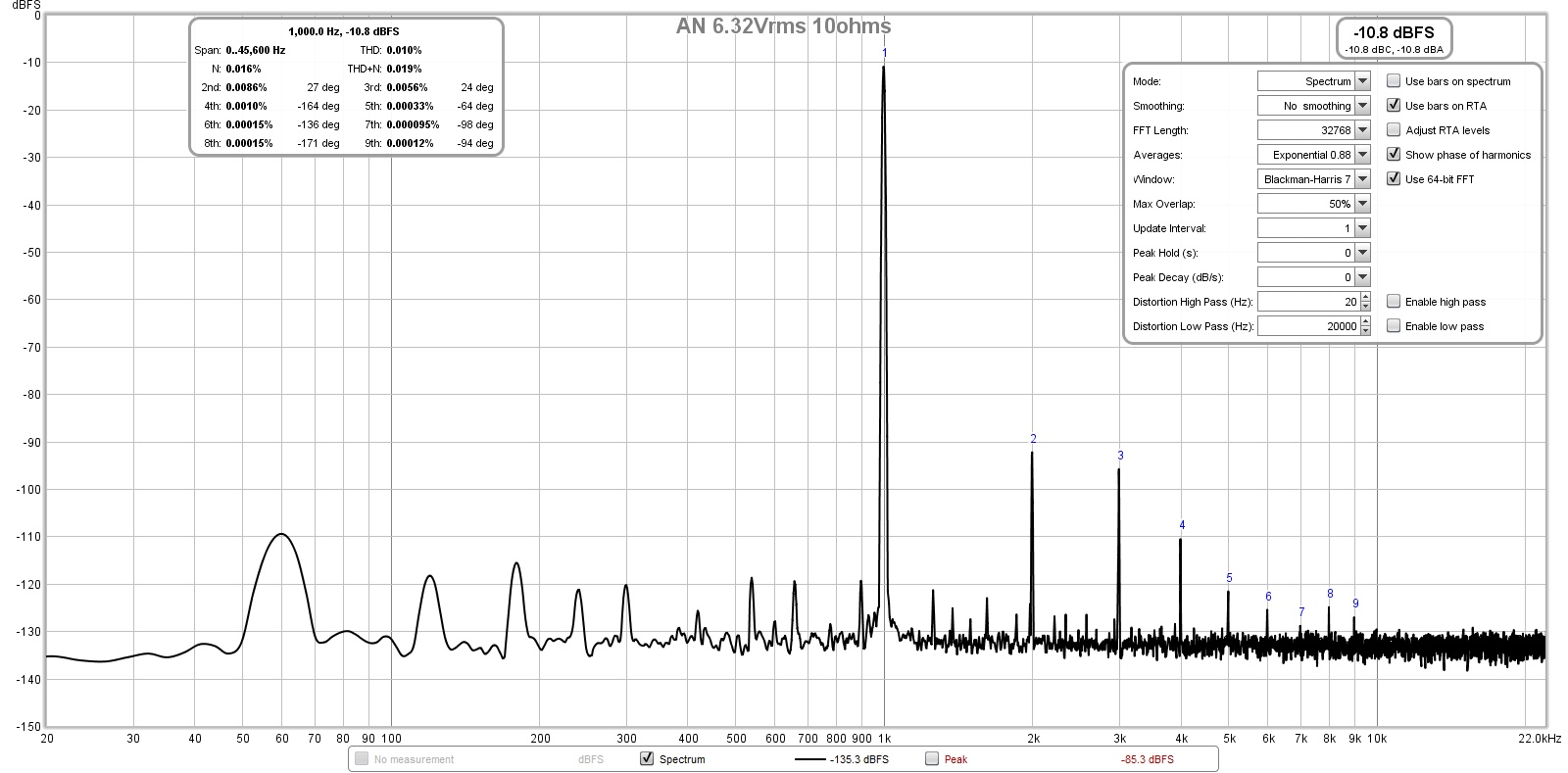
This is for 6.32vrms into 10ohms (4w) for 0.01% THD:
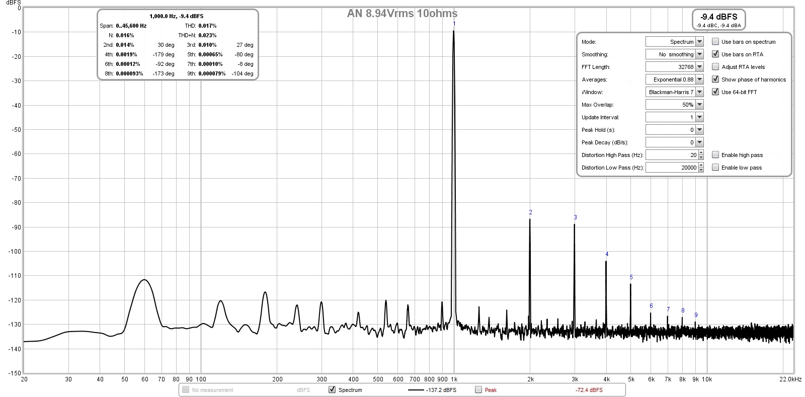
This is for 8.94vrms (10w) for 0.017% THD:
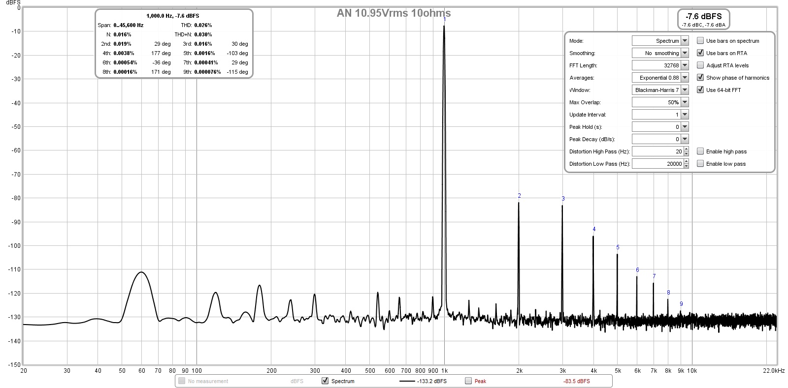
This is for 10.95vrms (12w) for 0.026% THD:
Here is the FFT for 2.83vrms into 10ohms (800mW) for 0.0045% THD:
This is for 3.16vrms into 10ohms (1w) for 0.0048% THD:
This is for 6.32vrms into 10ohms (4w) for 0.01% THD:
This is for 8.94vrms (10w) for 0.017% THD:
This is for 10.95vrms (12w) for 0.026% THD:
Attachments

Last edited:
Thank you X,
It doesn't get much better than that, although I'd love to knock down H3 by another 10dB. It's a very good profile, and with hum at -110dB I think this is an extremely quiet amp.
Any thoughts on the sound compared to the Alpha 20 and the BB?
Brilliant work, much appreciated.
Hugh
It doesn't get much better than that, although I'd love to knock down H3 by another 10dB. It's a very good profile, and with hum at -110dB I think this is an extremely quiet amp.
Any thoughts on the sound compared to the Alpha 20 and the BB?
Brilliant work, much appreciated.
Hugh
You are very welcome, Hugh!
I wonder if the H3 could be reduced by using Panasonic ERX resistors vs the white rectangular KOA Speer BPR's (for the MOSFET Source resistors) which are not metal thin film, but non-inuductive metal wire loop (nichrome or steel or something high resistance). That might be worth exploring - I think I have a few ERX left. They are starting to be classified EOL which is why we went away from them. They are not even in stock at Mouser anymore, and have a red "LC" lifecycle warning saying not recommended for new designs.
ERX-3SJR22V Panasonic | Mouser
Last edited:
You may well be right here. I have found source resistors have quite an effect on the H2/H3 level, and hugely different if they are not symmetrical.
HD
HD
- Home
- Amplifiers
- Solid State
- Alpha Nirvana 39w 8ohm Class A Amp