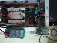
Well I guess I was closer to finishing the left channel amp than I thought, took 7 hours🙂
Performed the same start up sequence as the Right channel, no issues along the way.
Cooking right now, been about 30 mins.

No access to the borrowed Fluke dmm today, and the one I ordered hasn't arrived. So moving leads back and forth. Easier now that I know what to look for.
-313, +319, with -007.6mv offset right now. Closer than the right channel
So happy that both have powered up with no issues!
Now on to finishing switch circuit and exterior body skin!
Thanks everyone for all your help and comments so far!
Performed the same start up sequence as the Right channel, no issues along the way.
Cooking right now, been about 30 mins.

No access to the borrowed Fluke dmm today, and the one I ordered hasn't arrived. So moving leads back and forth. Easier now that I know what to look for.
-313, +319, with -007.6mv offset right now. Closer than the right channel
So happy that both have powered up with no issues!
Now on to finishing switch circuit and exterior body skin!
Thanks everyone for all your help and comments so far!
isn't it nice when they run smoothly the first time 🙂 congrats!
did you take any hum measurement of the output? with inputs shorted and inputs connected to the preamp. Just to make sure there are no ground loop issues
did you take any hum measurement of the output? with inputs shorted and inputs connected to the preamp. Just to make sure there are no ground loop issues
Thanks for the congrats and taking the time to comment!isn't it nice when they run smoothly the first time 🙂 congrats!
did you take any hum measurement of the output? with inputs shorted and inputs connected to the preamp. Just to make sure there are no ground loop issues
But I guess a little too early on the congrats. After a little over 2 hours of cooking I connected up to the speaker and preamp. Within about 5 seconds it blew the fuse. (Did play for the 5 seconds). I started with a 4 amp slow blow fuse, worked fine in the right channel.
I have swapped the power supply cord to same outlet as the right channel, swapped input cables and speakers from working amp to non working amp, no difference and first amp runs on all speakers and inputs.
Changed fuse to 5 amp slow blow, blew just as quick.
Then installed new 5 amp fuse, no speaker or preamp connected, and shorted input, blew the fuse.
Any advice on where to start troubleshooting?
I would start looking for any short circuit in the power supply and would also check the bridge rectifiers.
You have one working channel for reference if in doubt
You have one working channel for reference if in doubt
Might want to ohm out and check if there are any shorts between the output transistors and the heat sink. That'll blow fuses quick.
Thanks for the input. I started double checking everything. Confused how everything can power up, heat up, bias as expected, but then blow a fuse with input.Might want to ohm out and check if there are any shorts between the output transistors and the heat sink. That'll blow fuses quick.
Luckily (I think) the first one is running correctly so I can compare. Using my dmm and checking for differences I found one. With the setting on Ohms and one lead to ground measuring the good amp to O/P I get 0.069 on the bad amp I'm showing a dead short.
Unsoldered the O/P connection from the P channel at the Output board. Now getting 0.069 on the Output board and a dead short on the P channel connection wire. Now to figure out why.
Go to the transistors, and check if their metal contact plates are shorting to the heatsink or not. There should be a small 1/2 moon cut in their sides so you can get to the back of the transistor with your probe.
Try to do the same with the diodes. ( I believe it is pin 2 that connects to the metal body of the diode. )
Try to do the same with the diodes. ( I believe it is pin 2 that connects to the metal body of the diode. )
Last edited:
The MIDDLE lead out connects to the backplate of the Power Device.
This middle lead MUST be INSULATED from Chassis.
This middle lead MUST be INSULATED from Chassis.
You said AFTER it sat for 2 hours you connected everything...
You would never want to plug or unplug an amp with it turned on
The interconnects should be in place before the amp is turned on
A nasty pulse can destroy input trannies
Regards
David
You would never want to plug or unplug an amp with it turned on
The interconnects should be in place before the amp is turned on
A nasty pulse can destroy input trannies
Regards
David
Thanks all for your comments, and I really appreciate the time you all take to read and comment on my build!
So to my problem (resolved BTW), a visual inspection showed no loose wire strands or any obvious issue. So I unscrewed the P channel heatsink, luckily I left a little extra length on the connecting wires, and started unbolting the transistors one by one with Dmm connected to show short. Thought I was wasting my time, until the last one (naturally). As soon as I loosened it just an 1/8" of a turn the meter cleared. Pulled the transitor completely loose and found this tiny piece of aluminum trash

Put back together with a new pad of Keratherm on now all is good!
FYI, I haven't completed my switch circuit, so I'm using the switch on a power strip. But before I power off I turn the pre off first. Then before I start up again I wait at least 10 mins to let the amps reset.
So to my problem (resolved BTW), a visual inspection showed no loose wire strands or any obvious issue. So I unscrewed the P channel heatsink, luckily I left a little extra length on the connecting wires, and started unbolting the transistors one by one with Dmm connected to show short. Thought I was wasting my time, until the last one (naturally). As soon as I loosened it just an 1/8" of a turn the meter cleared. Pulled the transitor completely loose and found this tiny piece of aluminum trash

Put back together with a new pad of Keratherm on now all is good!
FYI, I haven't completed my switch circuit, so I'm using the switch on a power strip. But before I power off I turn the pre off first. Then before I start up again I wait at least 10 mins to let the amps reset.
That's exactly what I thought. Well done on choosing the fuses. They are sized to protect your work.
That happened to me too: I screwed the transistor to the case, measured, then gave it another twist without measuring. The second twist caused the swarf to pierce the keratherm. But, I did not have proper protection in place, so the transistors blew.
That happened to me too: I screwed the transistor to the case, measured, then gave it another twist without measuring. The second twist caused the swarf to pierce the keratherm. But, I did not have proper protection in place, so the transistors blew.
Thanks for helping me through the build! A 4 amp slow blow holds and does protect. Slow charge and soft start work great! I'm surprised for as large of transformer and size of my cap bank.That's exactly what I thought. Well done on choosing the fuses. They are sized to protect your work.
That happened to me too: I screwed the transistor to the case, measured, then gave it another twist without measuring. The second twist caused the swarf to pierce the keratherm. But, I did not have proper protection in place, so the transistors blew.
Been running as a system now for about 2 1/2 hours straight. Sounds really great. Plays loud enough and even at moderate level sounds full and not thin like most I've heard in my system.
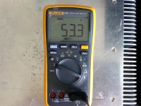
Biased at 0.315 right now and hottest part of sink is 53.3C. Right in middle of design of 50-55C.

New meter arrived yesterday! Just in time.
So to my problem (resolved BTW), a visual inspection showed no loose wire strands or any obvious issue. So I unscrewed the P channel heatsink, luckily I left a little extra length on the connecting wires, and started unbolting the transistors one by one with Dmm connected to show short. Thought I was wasting my time, until the last one (naturally). As soon as I loosened it just an 1/8" of a turn the meter cleared. Pulled the transitor completely loose and found this tiny piece of aluminum trash
.
Funny how that happens. It is hard to diagnose sometimes too. Happened to BigE too. Goes to show, its very important to clean the surfaces before you install the FETs and diodes to the heatsink.
For good practice sake, I generally take an alcohol pad and wipe the two surfaces before installing anything to the heatsink.
Congrats on the build!
Not sure what the ambient temperature is but at 53.3C, 0.315V bias is as high as I would dare take it. It should be plenty of power... about 100Wrms into 8 ohms.
Of course if you want more gain you can always increase the feedback resistance 😀
Oh, I was looking at the completed pics again, do you have perforation, or at least vent holes on the top and bottom plates? I don't seem to see any, if you are up for more fabrication, added venting there may be able to help with cooling.
Last edited:
Thanks for your comments and taking time to reply!Carefully place thermocouple on pin 2 of any Mosfet. Verify you are no hotter than 65C.
Your comment brings up a good question. In the Firstwatt paper about the F5's the heatsink temp is to be between 50-55C. Where is this measurement taken from? At the tip of the sink or the body part of the heatsink just behind the transistor?
I can't get to any of the pins as I have shrink wrap on them plus the little heatsinks.
Just got back from a long brunch with the family (still a fraidy cat to leave on when I'm away), I have the tip of the thermocouple to the tip of the screw holding the transistor to the heatsink. This is going to be the closest I can get to the transitor. After 20 mins it's showing 48.1 and slowing moving up still.
The 53.3C that I posted earlier was with the tip of the thermistor to the back body of the heatsink. At the tips the heatsinks measured around 47C
Thanks again for the advice and input.
Dazed2, thanks for the reply.Funny how that happens. It is hard to diagnose sometimes too. Happened to BigE too. Goes to show, its very important to clean the surfaces before you install the FETs and diodes to the heatsink.
For good practice sake, I generally take an alcohol pad and wipe the two surfaces before installing anything to the heatsink.
Congrats on the build!
Not sure what the ambient temperature is but at 53.3C, 0.315V bias is as high as I would dare take it. It should be plenty of power... about 100Wrms into 8 ohms.
Of course if you want more gain you can always increase the feedback resistance 😀
Oh, I was looking at the completed pics again, do you have perforation, or at least vent holes on the top and bottom plates? I don't seem to see any, if you are up for more fabrication, added venting there may be able to help with cooling.
Funny thing is I was extremely careful, I had a can of the pressurized computer cleaner and used alcohol on some face scrubbing cotton pads I stole from my wife to wipe down everything. I don't know how I missed it! I had read about other builds where stray strands of wire fried parts, so I really tried to be careful.
Thanks for the congrats! At the time of my measure this morning it was 26.6C in the condo with a little ocean breeze from the window in the living room.
I just posted that I'm not sure where to measure the temp at on the heatsink. After I get more comfortable with how the amps react to change and know where to measure I can adjust accordingly. I still have the dmm's connected and so I can't completly close the lid. The top and bottom do not have ventilation, on purpose. The fan pushes outside air into the chassis and exits through the small slot between the upper and lower sink. With the lid on the air escaping through the top and not helping cool the heatsinks.
Measure the hottest part of the heatsink, it should be right next to the transistor.
As for transistor itself, try the plastic body if you don't want to peel back the heat shrink to test.
As for transistor itself, try the plastic body if you don't want to peel back the heat shrink to test.
That data sheet for the MUR3020W says 175C max operating temp. After 45 mins the Toshibas are about 40C and the MUR3020W's are about 49C as measured on the body. Measuring now to the tip of the screw holding the MUR3020W's is about 55C. Which is the hottest part of the heatsink right know.Measure the hottest part of the heatsink, it should be right next to the transistor.
As for transistor itself, try the plastic body if you don't want to peel back the heat shrink to test.
So am I correct that the 50-55C temp in the firstwatt paper refers to the outside edge of the heatsink? That's the only part you would be able to touch for 10 seconds.
And not exceed 60C on the body of the transistor? Why not go up to 175C?
And not exceed 60C on the body of the transistor? Why not go up to 175C?
You could drive on the highway in 2nd, at redline, but your car wouldn't last very long...
Same reason, longevity and reliability. To keep these things from failing often and expensively, it's best to run them conservatively, which is 65C max pin 2 and no more than about 1/3 max dissipation continuously.
And anyway, do you want your amp to be 350deg F to the touch??
😱😱😱
- Status
- Not open for further replies.
- Home
- Amplifiers
- Pass Labs
- Aloha F5 v3 Monoblock build