The F5 has a 1pr output stage.
since the feedback resistor currents are tiny, you know that the Nchannel current is virtually the same as the pchannel current.
The Vdrop error on the source resistors must be the resistor value mismatch.
This does not affect the operation of a 1pr output stage.
If and when you build a multi-parallel output stage, both mosFET and BJT, then matching of the source/emitter resistors becomes more important.
An example I gave in a report a few years back.
I matched the 4pr output stage of lateral mosfets.
I matched all the quads of source resistors.
Powered up and set the output bias current. 7 of the lateral mosFETs had very similar source resistor Vdrop. one was/is miles out. actually 30% more bias current than it's 3 partners. This device runs much hotter than it's partners.
This device is more highly stressed than any of the other 7 output devices.
If the source resistors had not been matched, then I would not have known this.
Ignorance of this potential problem is not bliss !
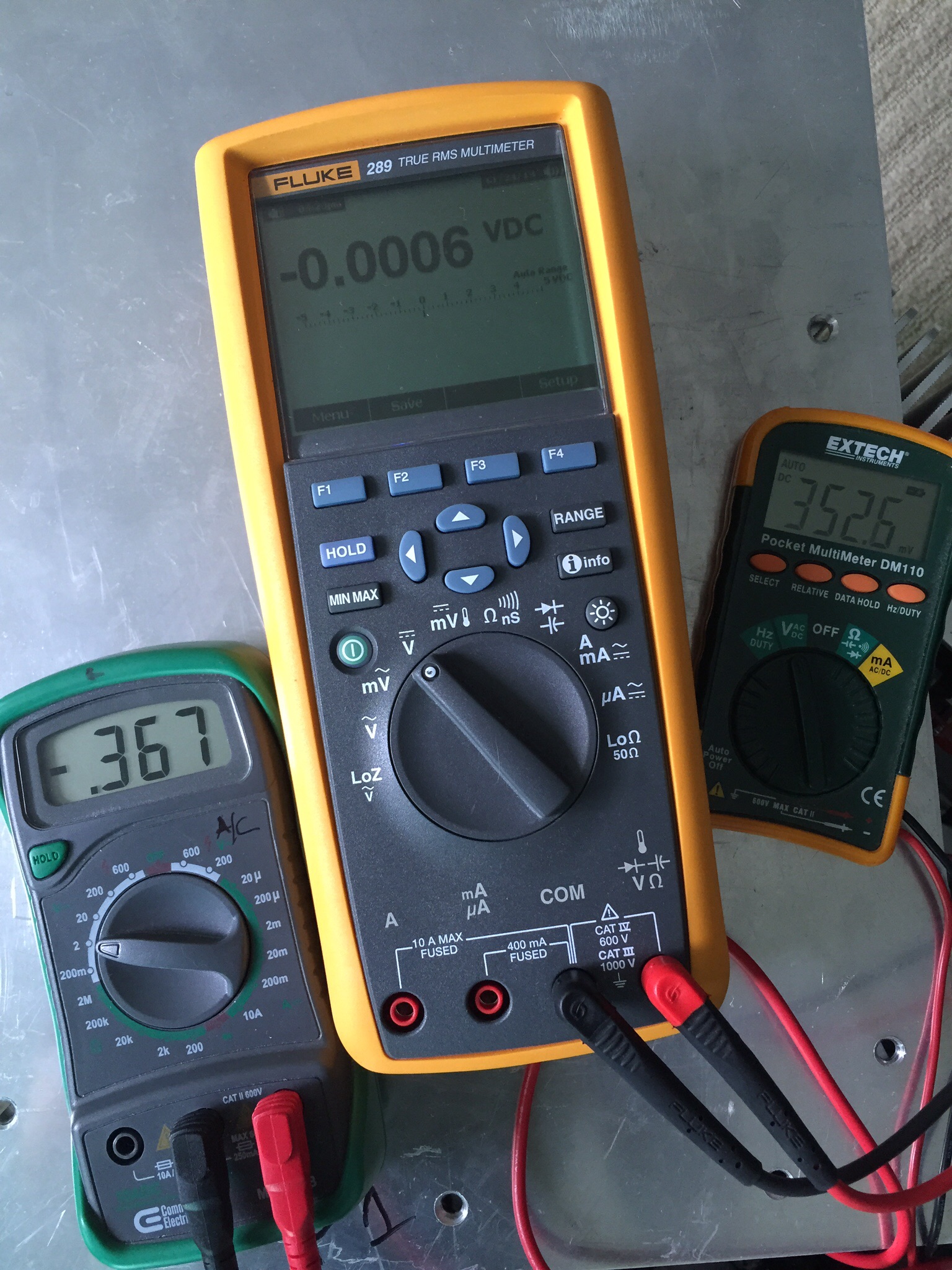
I had about 40 mins to try and rebalance the bias and offset before I had to run to the airport. After letting it run for about 20 mins to settle in I was able to get these numbers
View attachment 450599
I didn't have time to check the source resistors. Is the relationship between N and P to extreme, or tolerable? Now that I have zero offset.
Thanks!
That looks a lot better, 6mV offset.
In my build I get a max of about 10mV difference from N and P channel bias.
As AndrewT says that could be the tolerance stack of jfets, MOSFETs, and source resistors, and perhaps even some of the other components .
I don't have a multimeter that can measure 1 ohm resistors with any great accuracy (ie. 0.001 ohm) and the probe resistance already measures 0.3 ohm so for me matching say 1% or less is kinda futile. So I tolerate the 10mV difference in bias voltage.
The difference in bias voltage is normal and is greatly effected by the difference in Vgs of the P vs. the N channel parts.
Don't worry about it. With thermal stability when warm and lid on, and zero offset, it's good. 🙂 🙂
Don't worry about it. With thermal stability when warm and lid on, and zero offset, it's good. 🙂 🙂
difference is 4%
go figure
😉
The F5 has a 1pr output stage.
since the feedback resistor currents are tiny, you know that the Nchannel current is virtually the same as the pchannel current.
The Vdrop error on the source resistors must be the resistor value mismatch.
This does not affect the operation of a 1pr output stage.
That looks a lot better, 6mV offset.
In my build I get a max of about 10mV difference from N and P channel bias.
As AndrewT says that could be the tolerance stack of jfets, MOSFETs, and source resistors, and perhaps even some of the other components .
I don't have a multimeter that can measure 1 ohm resistors with any great accuracy (ie. 0.001 ohm) and the probe resistance already measures 0.3 ohm so for me matching say 1% or less is kinda futile. So I tolerate the 10mV difference in bias voltage.
The difference in bias voltage is normal and is greatly effected by the difference in Vgs of the P vs. the N channel parts.
Don't worry about it. With thermal stability when warm and lid on, and zero offset, it's good. 🙂 🙂
Thanks all for the input and taking the time to read and answer my questions.
I guess now I'm ready to connect to a preamp and speaker? I haven't populated the speaker protection boards yet so I'll wait till the amp is up to temp and stabilized before connecting the speaker.
Any input on my temperature readings? On adjusting the bias, what is the indicator that I'm close? I understand 0.4 is max and 0.3 is a good starting point. My last numbers were .367 and .352, averaged 359.5, should I leave it there or??
Temp - can you keep your hand on the heatsinks for 10 or more seconds? If so, you're good.
Bias - Leave it where it is for awhile, it's about perfect.
Bias - Leave it where it is for awhile, it's about perfect.
Thanks for the reply, I'll leave it be.Temp - can you keep your hand on the heatsinks for 10 or more seconds? If so, you're good.
Bias - Leave it where it is for awhile, it's about perfect.
But where does this put me? Somewhere between FAB (fearless amp builder) and Fraidy-Cat? 😕
Not at all - read Nelson's original F5T article, and there is a part where he talks about bias amount and getting the diodes to conduct - you can't turn up the wick as much as your heatsink can allow on a Turbo because you will turn the diodes on just with bias, and then things really interesting when a big-ish signal gets applied.
You probably can turn things up higher, but honestly, there's no real advantage. Much more gain in sound quality can be had by making a probe, getting some FFT software, and setting P3 to taste.
You probably can turn things up higher, but honestly, there's no real advantage. Much more gain in sound quality can be had by making a probe, getting some FFT software, and setting P3 to taste.
It's alive and playing music!Not at all - read Nelson's original F5T article, and there is a part where he talks about bias amount and getting the diodes to conduct - you can't turn up the wick as much as your heatsink can allow on a Turbo because you will turn the diodes on just with bias, and then things really interesting when a big-ish signal gets applied.
You probably can turn things up higher, but honestly, there's no real advantage. Much more gain in sound quality can be had by making a probe, getting some FFT software, and setting P3 to taste.
Running the left channel on a Proceed HPA2 and the right on the F5turbo v3. Went ahead and added a single ended RCA input and the Proceed has the option of either so I can compare apples to apples.
Too early to make any real comparisons, but the turbo sounds fuller and rich.
Thanks so much!Congratulations on a very smooth build!


Been running with music through it for about an hour now. Still passes the 10 second rule, with a little to spare (but not much)
I turned off the A/C, made sure all windows were closed to get the room as quiet as possible, left everything connected and paused the music at the source. With my ear to each driver no sound. (Actually have sound I can hear from about a foot away on the Proceed side). I can however hear the fan up close, but not from sitting position. Need to add the resistor.
Playing music on low volume and up to 98 decibels. Everything good so far!

Now on to completing the other amp. But it's only about 8 hours of work behind this one.
Some DMMs have inputs for temperature sensors. Just stick on in a screw hole in the heatsink, or tape it to the top of heatsink.
This is better than the 10 second rule, as that varies with your pain tolerance.
I would run it at 0.3 volts first. It *will* drift, and you don't want it to drift to 0.4.... 0.3 is far enough away.
Remember, the temp will vary with the ambient temp of the room. You should ensure that it has enough space beneath it as well as above for good airflow.
Thanks for the advice! Yes it has drifted up already some, had to drop it down a couple points.Some DMMs have inputs for temperature sensors. Just stick on in a screw hole in the heatsink, or tape it to the top of heatsink.
This is better than the 10 second rule, as that varies with your pain tolerance.
I would run it at 0.3 volts first. It *will* drift, and you don't want it to drift to 0.4.... 0.3 is far enough away.
Remember, the temp will vary with the ambient temp of the room. You should ensure that it has enough space beneath it as well as above for good airflow.
Watching still with dmm' attached. Probably another hour, then done for the night.
I need to find a dmm with temp probe, your right about pain tolerance, I might have 3rd degree burns proving its in compliance!
I need to find a dmm with temp probe,
I found one -
The temp function is the thermometer symbol near mV. The thermocouple is likely in the bag with the other probes. 🙂
That would be too easy!I found one -
The temp function is the thermometer symbol near mV. The thermocouple is likely in the bag with the other probes. 🙂
I borrowed the Fluke from a friend, I guess he either didn't buy or lost the temp probe.
I bought another Fluke (not as expensive as the one I borrowed) but with temp probe, should be here in a couple days. Maybe I'll have the left channel done by then.
Thanks for the advice! Yes it has drifted up already some, had to drop it down a couple points.
Watching still with dmm' attached. Probably another hour, then done for the night.
I need to find a dmm with temp probe, your right about pain tolerance, I might have 3rd degree burns proving its in compliance!
Keep the probes connected and place the cover on. let it run for 24 hrs and recheck bias. It will drift. Rebias and then keep it on for a week. It should drift a little again.
After a month check bias one more time, and it should be stable.
Congrats on the build!
Dazed2 thanks! I'm afraid to run it when I'm not home, but I will continue to run it as much as possible, especially while I complete the left channel.Keep the probes connected and place the cover on. let it run for 24 hrs and recheck bias. It will drift. Rebias and then keep it on for a week. It should drift a little again.
After a month check bias one more time, and it should be stable.
Congrats on the build!
It's been fun building so far.
How do I determine output watts, input and output impedance? I need to start learning how this works and what I need to look for in making adjustments to either the amp or my preamp and/or custom cabling between the two.
the PSU gives the voltages on the output devices.
The output can not be higher than the PSU voltage.
The PSU voltage will sag when you ask full power to be delivered.
expect 3Vdc to 10Vdc of sag from quiescent voltage to full power voltage.
The transistors and resistors and cabling will lose a bit of voltage when delivering high current to the load.
Expect 2Vdrop to 6Vdrop through the amp to the load when delivering full power.
The total drop in voltage from quiescent PSU voltage to maximum output voltage will be from [3+2] V to [10+6] V i.e your peak output voltage will be between 5V and 16V below the PSU quiescent voltage.
P = V²/R = I²R = VI
For the peak values of a sinewave this becomes
P = Vpk²/R/2 = Ipk²R/2 = VpkIpk/2
Using Vpsu = +-60Vdc, Vpk = Vpsu-10Vdrop and R = 8ohms speaker load
maximum Power = [60-10]²/8/2 = = 2500/16 = 156W
The only way to confirm that, is to measure the maximum unclipped output voltage Vpp into your 8r0 dummy load. You need an oscilloscope, and adjustable sinewave source and an AC voltmeter.
Vpp = 2*Vpk = 2*sqrt(2)*Vac when the signal is a sinewave.
BTW,
I built up a Leach Lo Tim clone and reported the results a few years ago.
I got, unclipped, very slightly more 170W into 8r0 using a PSU that measured +-58.5Vdc (40+40Vac transformer)
The maximum unclipped Vpk into 8r0 to get that 170W is 52.15Vpk (I think the actual output voltage was 37.0Vac = 104.6Vpp)
i.e. I lost a total of 58.5-52.15 = 6.3V, due to sagging PSU and losses through the amplifier.
Some amp builds can get a little bit better.
Many amp builds get a much worse result. The maximum voltage collapses due to the inability to deliver current !
Last edited:
Thanks for the information. My HIFI friend has a scope I can borrow. I don't know how to use it or set it up, so on to more education!the PSU gives the voltages on the output devices.
The output can not be higher than the PSU voltage.
The PSU voltage will sag when you ask full power to be delivered.
expect 3Vdc to 10Vdc of sag from quiescent voltage to full power voltage.
The transistors and resistors and cabling will lose a bit of voltage when delivering high current to the load.
Expect 2Vdrop to 6Vdrop through the amp to the load when delivering full power.
The total drop in voltage from quiescent PSU voltage to maximum output voltage will be from [3+2] V to [10+6] V i.e your peak output voltage will be between 5V and 16V below the PSU quiescent voltage.
P = V²/R = I²R = VI
For the peak values of a sinewave this becomes
P = Vpk²/R/2 = Ipk²R/2 = VpkIpk/2
Using Vpsu = +-60Vdc, Vpk = Vpsu-10Vdrop and R = 8ohms speaker load
maximum Power = [60-10]²/8/2 = = 2500/16 = 156W
The only way to confirm that, is to measure the maximum unclipped output voltage Vpp into your 8r0 dummy load. You need an oscilloscope, and adjustable sinewave source and an AC voltmeter.
Vpp = 2*Vpk = 2*sqrt(2)*Vac when the signal is a sinewave.
BTW,
I built up a Leach Lo Tim clone and reported the results a few years ago.
I got, unclipped, very slightly more 170W into 8r0 using a PSU that measured +-58.5Vdc (40+40Vac transformer)
The maximum unclipped Vpk into 8r0 to get that 170W is 52.15Vpk (I think the actual output voltage was 37.0Vac = 104.6Vpp)
i.e. I lost a total of 58.5-52.15 = 6.3V, due to sagging PSU and losses through the amplifier.
Some amp builds can get a little bit better.
Many amp builds get a much worse result. The maximum voltage collapses due to the inability to deliver current !
- Status
- Not open for further replies.
- Home
- Amplifiers
- Pass Labs
- Aloha F5 v3 Monoblock build