The cap bank is supplying the full bias when it is initially turned off.
It will be discharged down to ~37% in one RC time constant.
If you have 25Vdc and a quiescent current of 2A, then the equivalent load resistance is 25/2 = 12r5
The RC time constant for a 60mF cap bank and 12r5 load would be:
RC = 0.06F * 12r5 = 0.75s, i.e. the 25Vdc will have dropped to ~9Vdc in 750ms.
In 5 times RC (~4s) the cap bank will be down to <5% of initial voltage if the load remains the same.
Thanks for the clarification.The cap bank is supplying the full bias when it is initially turned off.
It will be discharged down to ~37% in one RC time constant.
If you have 25Vdc and a quiescent current of 2A, then the equivalent load resistance is 25/2 = 12r5
The RC time constant for a 60mF cap bank and 12r5 load would be:
RC = 0.06F * 12r5 = 0.75s, i.e. the 25Vdc will have dropped to ~9Vdc in 750ms.
In 5 times RC (~4s) the cap bank will be down to <5% of initial voltage if the load remains the same.
So what could be the cause of the excessive heat/voltage going through the MUR3029's?
Thanks for the clarification.
So what could be the cause of the excessive heat/voltage going through the MUR3029's?
Were your temperature measurements with the 0.41V bias or with the new reduced 0.32V bias?
Now that you know how it sounds perhaps you should reduce the bias a bit more and let us know how the sound has changed if any.
Nash
Were your temperature measurements with the 0.41V bias or with the new reduced 0.32V bias?
Now that you know how it sounds perhaps you should reduce the bias a bit more and let us know how the sound has changed if any.
Nash
I don't remember going to 0.41 bias. I was at 0.367 when the temp ran to 55 C.
Honestly I have not heard a difference in lower/higher bias. But my system as a whole is still breaking in and been playing around with speaker placement. Critical listening still a month or so away, just happy the amps play right now!
Does R25 and R26 control voltage to the MUR3020's? I know there is a mixup in the BOM/schematic with R25 being 10k (correct) R26 being 47.5k (incorrect).
Because my rail voltage is higher I used 12k for both R25/26. Should this be higher?
Because my rail voltage is higher I used 12k for both R25/26. Should this be higher?
I don't remember going to 0.41 bias. I was at 0.367 when the temp ran to 55 C.
Honestly I have not heard a difference in lower/higher bias. But my system as a whole is still breaking in and been playing around with speaker placement. Critical listening still a month or so away, just happy the amps play right now!
In post #322 you mentioned bias closer to 0.4V; my mistake with the 0.41V.
R25 and R26 and their associates is for reducing the rail voltage to the Jfets which will then see less. You can easily check it on the FE board since it has an extra set of Jfet holes in it. Connect a voltmeter between the D hole and FE board Ground point to read the voltage to the Jfet.
Nash
What is the bias current? You have enough to get the diodes conducting, they are only supposed to do that on transients...
How do I measure bias current? What controls the current to the diodes?
How do I measure bias current?
Like this -
What controls the current to the diodes?
From Nelson's F5T manual - (Starting just above the schematic for the F5Tv2)
It looks just like V1 except that there are some diodes in parallel with the Source resistors of the output devices. These are some of those fancy new- fangled high speed power diodes from Vishay, MUR3020W, rated at 400A peak and having an equivalent resistance of about .03 ohms per parallel pair. Inserting these in parallel with the 0.5 ohm Source resistance gives us an impedance which is very low at high currents but devolves to the 0.5 ohm value at less than an amp.
The result is that the amplifier can now deliver 38 amp peaks:
Well, that was easy. The distortion character at ordinary power levels is pretty much the same, and ditto for bandwidth and such. Actually it's pretty much the same until you get a couple amps going to the load, and then the F5 Turbo starts flexing its newfound muscles.
You do have to watch a couple of things. Here is a curve from Vishay's spec sheet that gives the voltage drop versus current for different temperatures.
We see that these devices will slowly start conducting at voltages just above the idle voltage across the 0.5 ohm Source resistors. It will be necessary to heat sink these diodes, remembering that their case is electrically connected.
The point at which the diodes conduct is temperature dependent, so you will want to set the bias so that it makes a nice transition above the bias point and doesn't run away when the amplifier gets hot.
If you are competent, fearless and also own a fire extinguisher, you can find this point. Just run the amplifier into a reasonably low impedance until it gets good and hot – as hot as you plan to let it get - ever. Then adjust the bias to a point below where the idle current starts to really take off. You should find that this point is around 0.4 volts across the 1 ohm resistors. If you are a fraidy-cat, then just set it at 0.3 volts, and conservatively fuse the AC line.
The cliff notes version: Reduce your bias a bit until the diodes are not too hot.
Thanks so much for taking the time to put together this answer!From Nelson's F5T manual - (Starting just above the schematic for the F5Tv2)
It looks just like V1 except that there are some diodes in parallel with the Source resistors of the output devices. These are some of those fancy new- fangled high speed power diodes from Vishay, MUR3020W, rated at 400A peak and having an equivalent resistance of about .03 ohms per parallel pair. Inserting these in parallel with the 0.5 ohm Source resistance gives us an impedance which is very low at high currents but devolves to the 0.5 ohm value at less than an amp.
The result is that the amplifier can now deliver 38 amp peaks:
Well, that was easy. The distortion character at ordinary power levels is pretty much the same, and ditto for bandwidth and such. Actually it's pretty much the same until you get a couple amps going to the load, and then the F5 Turbo starts flexing its newfound muscles.
You do have to watch a couple of things. Here is a curve from Vishay's spec sheet that gives the voltage drop versus current for different temperatures.
We see that these devices will slowly start conducting at voltages just above the idle voltage across the 0.5 ohm Source resistors. It will be necessary to heat sink these diodes, remembering that their case is electrically connected.
The point at which the diodes conduct is temperature dependent, so you will want to set the bias so that it makes a nice transition above the bias point and doesn't run away when the amplifier gets hot.
If you are competent, fearless and also own a fire extinguisher, you can find this point. Just run the amplifier into a reasonably low impedance until it gets good and hot – as hot as you plan to let it get - ever. Then adjust the bias to a point below where the idle current starts to really take off. You should find that this point is around 0.4 volts across the 1 ohm resistors. If you are a fraidy-cat, then just set it at 0.3 volts, and conservatively fuse the AC line.
The cliff notes version: Reduce your bias a bit until the diodes are not too hot.
So I haven't done anything wrong, I just need to set the bias to the point that the diodes don't heat the heatsink temp above 50-55C?
I have also ordered the Noctua fan, as earlier suggested by others, fan still too noisy.
My design with the fan and the slot through the opening between the sinks really makes a difference. If I take the lid off, even with the fan still running, the temp and bias climbs higher than with the fan on and the lid on.
I will play with that a little more after I install the new fans.
My design with the fan and the slot through the opening between the sinks really makes a difference. If I take the lid off, even with the fan still running, the temp and bias climbs higher than with the fan on and the lid on.
When opening the lid you are changing the airflow across the thermistors, changing the bias.
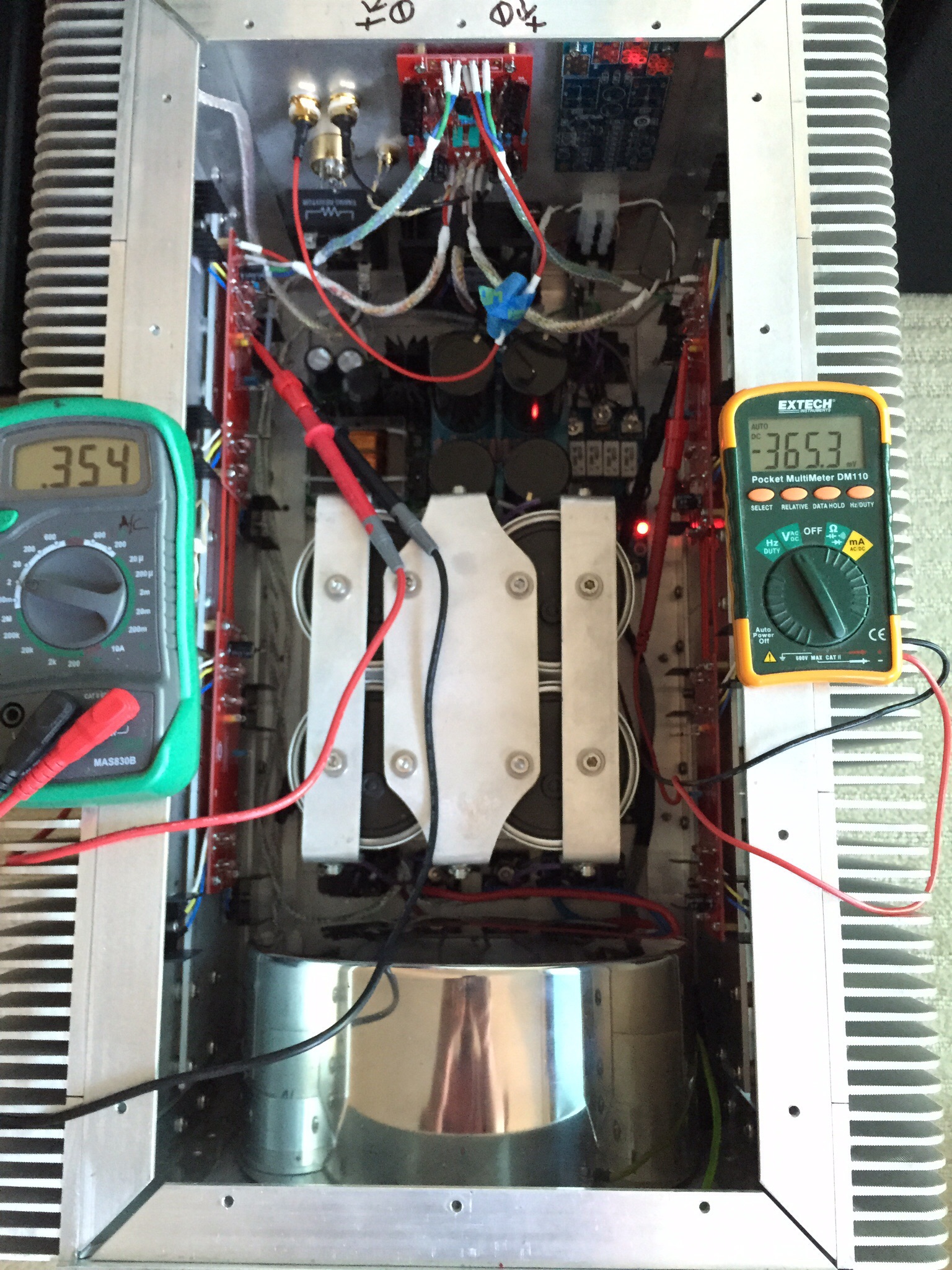
And the DC offset can also be affected. On one channel, I must set the DC offset to about 35 mV with the lid off. Then, when the lid is put back on, the DC offset moves to near zero.
I have been enjoying listening to the amps for the past couple of weeks while I was working on my SP10 MK2 turntable project. The bias has been close to stable the last week or so.
Since I hadn't finished the planned momentary switch with control board and transformer board from AMP.org yet I have been physically plugging/unplugging them. I was having a hard time working with the small parts and connectors on the AMP boards and designing the faceplate around the switch. So I nixed that plan.
Instead I installed a toggle switch, placed on the back, that turns on/off the 12vdc power supply I bought from K&K Audio. Besides the fan this power supply controls 3 relays. One relay is the "switch" for the DIY Audio soft start board. The other two relays bypass the pair of Ametherm MS35's that are my "slow charge" circuit for the large cap bank. I have a solid state timer that engages the relays after about 30 seconds from turn on. I am using a 5 amp slow blow fuse and have not killed a fuse yet, so the soft start and slow charge circuits are performing as planned. The next time I think about it I will try out a 4 amp to see if it holds, might offer a little more protection.
I also changed out my original fan for a Noctua fan. Besides being almost silent it also moves more air. The sound it does put out is much deeper and so less noticeable. Too much ambient noise this evening for an absolute review, but I couldn't disern a fan noise from 2' away.
I played the amps for an hour tonight after this round of changes and on the left amp I had 0.337 bias and temp of 49.1 Celsius. The right amp had 0.366 bias and 47.9 Celsius. Not sure why the right amp is running cooler with more bias. In the next day or two I'll adjust the bias to 0.350 each and see what the temp does and compare again.
I wonder if adding a window comparator to monitor the two output bias resistor voltage drops would give any worthwhile detection mode/s?
Two stages of comparator, narrow window to trigger a flashing light (non latching to turn off if the bias returns to normal) and a wider window to trigger a latching power OFF relay.
Two stages of comparator, narrow window to trigger a flashing light (non latching to turn off if the bias returns to normal) and a wider window to trigger a latching power OFF relay.
Try measuring the temps of the transistors themselves, not the heatsink. When you measure the heatsink, you also measure how well the transistors are thermally coupled to the heatsink.
Poor contact = lower heatsink temp.
Poor contact = lower heatsink temp.
I have been running the bias at 0.35 the last couple days and the heatsinks measure average of about 48 Celsius. The new fan has helped drop the temps some. The temp on the transistor body run about 10 degrees hotter.
I'm close to being ready to try and adjust P3. I have been reading for the last 2-3 hours about the process, but I can't understand exactly what I need to buy and how to connect. I watched 6L6's YouTube video again, and I think I understand what to look for on the screen. And I have read some of BigE's posts.
Can I use just my scope? I have a Mac mini and a laptop. Can anyone one post a step by step?
P3 changes the distortion behaviour of the amplifier.
The only way to adjust is by measuring the distortion.
Then listen.
If you want to return to a previous setting you need to know what distortion that setting gave and try to get back to that distortion point by re-measuring as you adjust.
You cannot do this with only an oscilloscope.
You cannot do this by ear.
Can I use just my scope? I have a Mac mini and a laptop. Can anyone one post a step by step?
Minimum tools needed -
(computer based)
Signal generator
Load resistor
Soundcard probe
Soundcard FFT software (Electroacustics Toolbox for Mac)
(Vintage boatanchor based)
Signal generator
Load resistor
Distortion analyzer (HP 339A, 8903A,B, Tektronics AA501A, etc...)
Scope
The tools are the hard part. The procedure is easy.
1K sinewave into amp of sufficient amplitude to give 1W into the load resistor.
Attach probes to resistor
Adjust P3 for desired distortion spectra. (which you read through the distortion analyzer or soundcard probes)
Last edited:
I have finally gotten back to working on the F5. Been working great and listen to it almost everyday. As it sits, it's a big ugly lump of aluminum with a lot of heat sink attached. And I still haven't adjusted P3 yet.
I have had a hard time coming up with a design that I like for more that a week of two. So I settled on making it look similar to my turn table.
Basically a bunch of MDF cut and routed to cover the four sides and leave open the actual sides with the heat sinks. Also set the top and bottom of the sides at a 45 degree angle to slow better airflow.
Raw form

After one round of primer and sanding and then the next round of primer still in the booth.


The top, front and rear will also have some brushed/anodized aluminum panels, and the top and front will also have some glass. The rear panel is removable to allow the amp to slide into place. The aluminum panel will cover most of the seam and the temp screws will be removed. Should look interesting when done. Hope to sand and spray out the silver and clear coat next weekend.
Sent from my iPad using Tapatalk
I have had a hard time coming up with a design that I like for more that a week of two. So I settled on making it look similar to my turn table.
Basically a bunch of MDF cut and routed to cover the four sides and leave open the actual sides with the heat sinks. Also set the top and bottom of the sides at a 45 degree angle to slow better airflow.
Raw form
After one round of primer and sanding and then the next round of primer still in the booth.
The top, front and rear will also have some brushed/anodized aluminum panels, and the top and front will also have some glass. The rear panel is removable to allow the amp to slide into place. The aluminum panel will cover most of the seam and the temp screws will be removed. Should look interesting when done. Hope to sand and spray out the silver and clear coat next weekend.
Sent from my iPad using Tapatalk
Spent the day on the dress for the amps to slip into. Final sanding with 400 grit, then 2 coats of Audi Silver, final 2 coats of clear. Turned out well.

- Status
- Not open for further replies.
- Home
- Amplifiers
- Pass Labs
- Aloha F5 v3 Monoblock build