Thanks guys! I didn't actually mean to try and run up to 175C, but 65C is a really long way from 175C. Trying to understand the limits of the amp/components and everyone's experience.
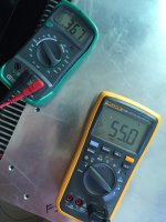
Just watched Django, through the amps/system. Sounded great! Also a long movie, after the movie the amps bias had increased to 0.316. The hottest point I could find was the body of the MUR3020W's which was 57.7C, the tips of the heatsink fins was 51.5C, and the hottest point on the body of the heatsink, which was on the backside of the MUR3020W's, was 55C
I'm guessing this is probably what I should stay at. With my subs and volume from the speakers, I still had plenty of volume knob left to go, and was probably close to the limit to anger the neighborhood!
Pretty excited about the whole build and the result!
Look at the datasheet..................And not exceed 60C on the body of the transistor? Why not go up to 175C?
The graph shows the de-rating for Tc.
When Tc=25°C the device can take upto 100% of it's power rating.
When Tc=175°C the device can take upto 0% of it's power rating.
Half way between these values, i.e. Tc=100°C the device can take upto 50% of it's maximum rating.
If you are using 30% as the quiescent dissipation and you have to de-rate to 50%, that leaves just 20% for the stresses due to the audio signal.
Andrew thanks for keeping up with my progress.Look at the datasheet.
The graph shows the de-rating for Tc.
When Tc=25°C the device can take upto 100% of it's power rating.
When Tc=175°C the device can take upto 0% of it's power rating.
Half way between these values, i.e. Tc=100°C the device can take upto 50% of it's maximum rating.
If you are using 30% as the quiescent dissipation and you have to de-rate to 50%, that leaves just 20% for the stresses due to the audio signal.
Going back to the original F5 paper Nelson writes
"As a rule of thumb, the output devices should not be operated at more than about half their maximum rating, and generally the case temperature needs to be under 100 deg C. For most amplifiers this means a heat sink temperature of about 50 to 55 deg C., which is the temperature that you can put your hand on for about 10 seconds."
Which I take goes along with what you just posted.
If the case of the output devices needs to stay under 100 deg C, I still have 40 deg C room to play with. Not that I plan to right now, but good to know.
I've run them about another 10 hours, bias has creeped up again to about .316 for each amp. Still sounding good. The original fan noise has died down some, might just leave them be, I can't hear them unless I'm standing over them now, must be breaking in?
Parts have come in for the switch circuit, so that's the plan for this weekend.
That 100°C is usually taken to be maximum junction temperature (Tj), rather than maximum case temperature (Tc).
A Sink temperature (Ts) at the interface of 50 to 55°C, gives very roughly 60 to 70°C for Tc.
That, when using the plot referred to earlier, becomes the temperature used for de-rating the ClassA output stage.
If Tc=100°C, then the devices need to be de-rated even more, leaving very little for the transient demands of the music.
heatsink at 55C max ,with properly mounted mosfets - recipe for long and satisfactory work
everything above that , trouble waiting around the corner
everything above that , trouble waiting around the corner
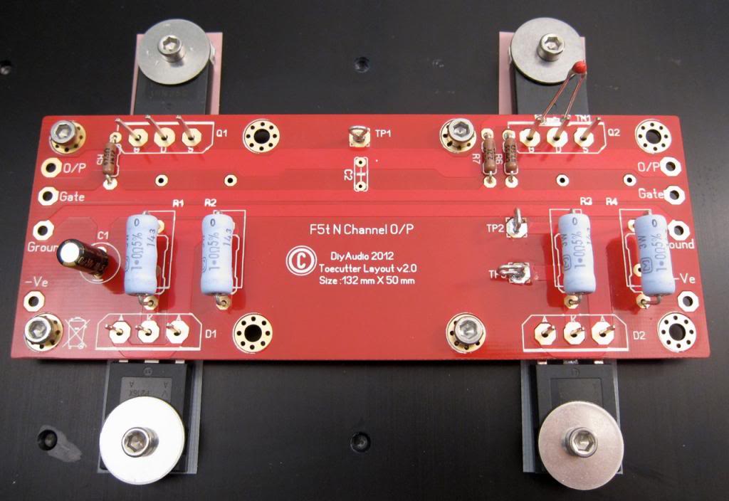
Also remember that in the Turbo implementation, the FET temperature is NOT the most important temperature to take into account. It is in fact the diode temperature.
If you look at the diode graphs you will find that at about 55-60C the forward voltage drop is at about 0.4V. When the diode starts to conduct at idle this is where thermal runaway happens and burns up the amp.
It is for this reason that NP suggests that you don't bias it so that the temp of the heatsinks go beyond 55C.
Of course you can always get around this by removing the diodes 😀 but then you won't be able to utilize the larger current capability that the 4pr MosFETs are able to handle.
That 100°C is usually taken to be maximum junction temperature (Tj), rather than maximum case temperature (Tc).
A Sink temperature (Ts) at the interface of 50 to 55°C, gives very roughly 60 to 70°C for Tc.
That, when using the plot referred to earlier, becomes the temperature used for de-rating the ClassA output stage.
If Tc=100°C, then the devices need to be de-rated even more, leaving very little for the transient demands of the music.
heatsink at 55C max ,with properly mounted mosfets - recipe for long and satisfactory work
everything above that , trouble waiting around the corner
Also remember that in the Turbo implementation, the FET temperature is NOT the most important temperature to take into account. It is in fact the diode temperature.
If you look at the diode graphs you will find that at about 55-60C the forward voltage drop is at about 0.4V. When the diode starts to conduct at idle this is where thermal runaway happens and burns up the amp.
It is for this reason that NP suggests that you don't bias it so that the temp of the heatsinks go beyond 55C.
Of course you can always get around this by removing the diodes 😀 but then you won't be able to utilize the larger current capability that the 4pr MosFETs are able to handle.
Thanks guys for taking the time to read and post!
I'll keep bias comfortably on the low side for the next month, then after its settled in good, I'll bump up closer to stay below the maximum temps.
Is about 100 hours enough time that the bias should stay put?
Time probably has some effect on achieving stability.
Repeated heating and cooling due to operating (both silent and reproducing music) and being off, probably has more effect.
Repeated heating and cooling due to operating (both silent and reproducing music) and being off, probably has more effect.
Just watched Django, through the amps/system. Sounded great! Also a long movie, after the movie the amps bias had increased to 0.316. The hottest point I could find was the body of the MUR3020W's which was 57.7C, the tips of the heatsink fins was 51.5C, and the hottest point on the body of the heatsink, which was on the backside of the MUR3020W's, was 55C
I am not sure why the hottest point is the body of the MUR3020W. The diodes will give out heat only when they start conducting which should be mostly on transients. What is the temp of the MUR3020W's in your PSU for comparison?
What was the hottest temp on the body of the Mosfet?
Nash
If the diode/s are hotter than the sink, then that must be due to the diodes passing current.
Investigate why and when the diodes are passing current.
If the diodes are getting too hot, then take them off the main heatsink and attach them to their own heatsink.
Investigate why and when the diodes are passing current.
If the diodes are getting too hot, then take them off the main heatsink and attach them to their own heatsink.
I am not sure why the hottest point is the body of the MUR3020W.
What is the bias current? You have enough to get the diodes conducting, they are only supposed to do that on transients...
As typical for me on technical questions I'm a little lost.
In my build the MUR2030's are on the bottom row of sinks. Moving the probe around they are the hottest point consistently, at 65 C. I don't have any MUR2030's in the PSU.
The bias has continued to creep up. While listening to records today I kept a close watch as it got closer to 0.4 and the heatsink temp moved up. This was after about 5 hours running today,

So bumped it back down to 0.32 again.
My HIFI friend came by today to listen to the new amps and turntable. He was happy with the results and spent an hour or two positioning my speakers, adjusting the subs amps, and general HIFI talk. Then out for Korean food, beer and Sake! Good day all around.
In my build the MUR2030's are on the bottom row of sinks. Moving the probe around they are the hottest point consistently, at 65 C. I don't have any MUR2030's in the PSU.
The bias has continued to creep up. While listening to records today I kept a close watch as it got closer to 0.4 and the heatsink temp moved up. This was after about 5 hours running today,

So bumped it back down to 0.32 again.
My HIFI friend came by today to listen to the new amps and turntable. He was happy with the results and spent an hour or two positioning my speakers, adjusting the subs amps, and general HIFI talk. Then out for Korean food, beer and Sake! Good day all around.
this confirms that the diodes are passing significant current for much of the time.In my build the MUR2030's are on the bottom row of sinks. Moving the probe around they are the hottest point consistently, at 65 C.
I don't think that is what is intended.
As I see it, the diodes are to help with power delivery on extreme transients.
And as such, they should pass significant current for very short periods on fairly rare occasions.
Yes, that is where I am attaching the probes.
I get similar results by measuring with the probes connected to each side of the source resistors.
Temperature does not seem to change whether playing music or just sitting without any input or output connections.
I have just a bit over 51v to the FE board, FYI.
I get similar results by measuring with the probes connected to each side of the source resistors.
Temperature does not seem to change whether playing music or just sitting without any input or output connections.
I have just a bit over 51v to the FE board, FYI.
Since both amps act exactly the same way, if the MUR2030's are not supposed to get this hot then I must have an incorrect component choice on the FE board.
Between 4 rails that all act the same and the simplicity of the board design, component value choice has to be wrong?
Between 4 rails that all act the same and the simplicity of the board design, component value choice has to be wrong?
- Status
- Not open for further replies.
- Home
- Amplifiers
- Pass Labs
- Aloha F5 v3 Monoblock build

