The brilliant mine from up north has spoken! It isn’t for the Aleph J PS for sure!! 😉 ; perhaps T4B is building a preamp as well?I'm wondering what the blue transformer is for?
Best,
Anand.

I‘m curious why the story of this build landed in this thread, instead of the one for ZM’s version of the Aleph J.
@Dennis Huinamghiwook, Please check the DC voltage at R11 or R12 - black probe at Ground, red probe at R11 or R12. What is the voltage? Does the voltage change if you adjust R7?
I used ZTX450, ZTX550.
@Ben Mah
1 turn of R7 changed about 3V of R11, R12.
ex.
R11 8.98V -> 9.28V
R12 8.94V -> 9.26V
and my BOM from 'Aleph J build guide for noobs'
Last edited:
Getting about 0.3V per turn seems about right, but the R11, R12 voltages seem wrong. I would have expected them to be in the -19V range (assuming ~ +/-23V rails).
Can you please measure your rail voltages on the amp PCB? Black probe on GND, red probe on V+ and V-.
Can you please measure your rail voltages on the amp PCB? Black probe on GND, red probe on V+ and V-.

What Dennis said.
Also:
Pay attention to polarity. Voltage should be negative.
1 turn of R7 changed about 3V of R11, R12.
ex.
R11 8.98V -> 9.28V
R12 8.94V -> 9.26V
That is a difference of only 0.3V, not 3V. If you turn it more, can you get it to -19V or so? Also measure the offset as you turn R7 further.
Also:
Pay attention to polarity. Voltage should be negative.
1 turn of R7 changed about 3V of R11, R12.
ex.
R11 8.98V -> 9.28V
R12 8.94V -> 9.26V
That is a difference of only 0.3V, not 3V. If you turn it more, can you get it to -19V or so? Also measure the offset as you turn R7 further.
Ah .. sorry! 0.3V per 1 turn of R7 is right.
The power rail is +/- 24.2VDC.
I adjusted R7 and made the R12 to -19VDC (red probe to R12 and black probe to GND)
DC offset remains -23.4VDC.
The power rail is +/- 24.2VDC.
I adjusted R7 and made the R12 to -19VDC (red probe to R12 and black probe to GND)
DC offset remains -23.4VDC.
Last edited:
I adjusted R7 and obtained dc offset voltage sudden back and forth range ... in about 1 VDC.
DC offset is not stable and so much sensitive to just a little turn of R7.
DC offset rises to over 10 VDC again.
Both heat sinks was warm.
I powered it up again and dc offset started at -23.4VDC and decreased to under 1VDC ... and not stable. ... and over 13VDC suddenly again.
DC offset is not stable and so much sensitive to just a little turn of R7.
DC offset rises to over 10 VDC again.
Both heat sinks was warm.
I powered it up again and dc offset started at -23.4VDC and decreased to under 1VDC ... and not stable. ... and over 13VDC suddenly again.
Last edited:
Can the offset be adjusted lower? Is there still some adjustment left in the pot?
Let it sit and heat up for a while before adjusting it further.
What voltage is at R11 or R12? Is it a negative value?
Let it sit and heat up for a while before adjusting it further.
What voltage is at R11 or R12? Is it a negative value?
R11, R12 is still -18.5 -19.5 negative values.
DC offset is so much sensitive to just a little turn of R7 and not stable and suddenly rises to 13~14VDC then I can not adjust dc offset properly.
I will try it again after reflow soldering and cleaning pcb.
DC offset is so much sensitive to just a little turn of R7 and not stable and suddenly rises to 13~14VDC then I can not adjust dc offset properly.
I will try it again after reflow soldering and cleaning pcb.
Last edited:
Are you monitoring the R11/R12 voltage at the same time (only need to monitor one or the other, no need to measure both)? If not, do so and see if that also changes drastically with the offset.
Yes, it is a good idea to check the solder joints.
Yes, it is a good idea to check the solder joints.
That's interesting. The original Zetex/Diodes parts use an E-line package while your earlier photos with Q2 and Q3 (https://www.diyaudio.com/community/attachments/20240325_014245-jpg.1290187/ and https://www.diyaudio.com/community/attachments/20240325_014216-jpg.1290186/ ) seem to show the 'round' side of the TO-92 package. And I have not found any second sources for those parts that might have used TO-92 instead.I used ZTX450, ZTX550.
I just want to make sure you don't have a pin-out problem with those transistors.
Those are parts. Porn implies joints. You read the wrong guide, should have been this one: https://www.mindbodygreen.com/articles/kama-sutraA little late night porn. The 2nd photo shows the resistors after I checked them against the BOM, as you can see I wrote down the values which saved a lot of time when stuffing the boards.
Finding the resistor locations from the board stencil often was more difficult to locate vs. locating it in the Guide.
Attachments
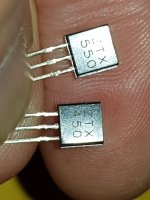
I’m curious if your ZTX series of transistors are genuine. They don’t look anything like the ones I have that I purchased from Mouser. Can others compare and let us know?
Do you have any BC550/560 transistors on your bench? They can also be used in the Aleph J circuit as substitutes. BC560 for Q2 and BC550 for Q3, Q4.
Best,
Anand.
Do you have any BC550/560 transistors on your bench? They can also be used in the Aleph J circuit as substitutes. BC560 for Q2 and BC550 for Q3, Q4.
Best,
Anand.
Fairly generic bipolars can be used in those positions. As long as their betas are not too low and their pinouts fit the PCB (i.e., the centre pin is base) they should work ok.
@namghiwook: Have you double checked the correct parts are in the right places and that all solder joints are ok? Also, where did you source the jfets?
@namghiwook: Have you double checked the correct parts are in the right places and that all solder joints are ok? Also, where did you source the jfets?
- Home
- Amplifiers
- Pass Labs
- Aleph J illustrated build guide