I have not used a SLB power supply and have only seen the forum thread. However I am always open to learning, and I appreciate TungstenAudio's and Zen Mod's input.

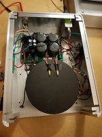
I'm using SLB without capacitor bank.
Can I find some pcb for capacitor bank or wiring diagram?
Can I find some pcb for capacitor bank or wiring diagram?
Attachments
Last edited:
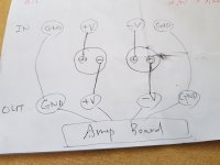
Can I use this Kemet Cap 40V 36000uf x 2 and capacitor clamps?
Is this wiring right?
https://www.mouser.kr/ProductDetail/?qs=AQlKX63v8RuS32uJ3T4X1w==
https://www.mouser.kr/ProductDetail/KEMET/PYC6041?qs=LbSuqLGD%2BvrgFAQPBszcwQ==
Is this wiring right?
https://www.mouser.kr/ProductDetail/?qs=AQlKX63v8RuS32uJ3T4X1w==
https://www.mouser.kr/ProductDetail/KEMET/PYC6041?qs=LbSuqLGD%2BvrgFAQPBszcwQ==
Attachments

When I build amplifiers with my own pcbs, I put capacitors on the amplifier pcbs to filter the incoming power and also to provide a bit of local storage. Many of the amplifier boards that I see on the Pass Labs forum, including the Aleph J board, do not have power supply capacitors. Are the addition of power supply capacitors on amplifier boards not a good thing?
heck Ben, you know the answer
what's easy to mount on actual amp pcb, it's more to lull your conscience
what's really effective, hard to squeeze on amp pcb
and then, if everything else done properly, it's not that much of difference having local decoupling for really thirsty part of amp, while low energy stages/subcircs is easy to decouple......
When people are considering exotic parts and trying to squeeze out the best performance, I think good wire routing to minimize loop areas and local decoupling capacitors are the low hanging fruit.
I was just looking at the XA-25. The separate front end board appears to have 8X 3300uF caps, which is ~6 times more capacitance than what I've been putting on mine. The main PS PCB lives in the center as usual, with short runs to the OS boards.
That amp placed input circuitry right at the back plate where the analog signal enters the amp. The chances of any induced noise, or ground loop issues, are 0. The input circuitry PCB has its own power supply local pole, to ensure very low impedance at all frequencies. No reason to believe that Nelso hasn't paid attention to very high frequencies on this PCB... the signals are sent to output AMP PCB once the voltage level is bumped to VAS-like levels... completely immune to all noise/induced rubbish.
The PS PCB location and the associated wiring are done in that way to ensure serviceability, but there's 0 reason (apart from space) not to place the PS storage caps right where they should be... as close as possible to the transistors.... to which the current is provided.
The speakers' return is kept very short and is fed right where it should be fed... to the PS ground - directly.... NOT via AMP PCBs
... and then we see external power supply boxes on this thread.... vastly compromised ground returns... km-long power supply wiring... no local PS pole inside the AMP boxes, no decoupling of input (and VAS, if used).
... also, a routinely wrong way to couple speakers' negative return... This one would be the garnish..
But, one day... maybe... things may change.
Not everyone agrees with you that the speakers' negative return to the amplifier board is wrong.
Speaker negative connection at the amplifier board and located close to the speaker positive, and then keeping both wires twisted together all the way to the speaker connectors keep the loop area small, which is a good thing for lowest noise.
Speaker negative connection at the amplifier board and located close to the speaker positive, and then keeping both wires twisted together all the way to the speaker connectors keep the loop area small, which is a good thing for lowest noise.
Nonsense... you are just trying to stubbornly prove something here but lack understanding of the current flows in this case.
What you are suggesting would mean that the large speaker current swings would share the same ground wire (common/ground potential segment), coming from the PS PCB, as the reference ground wire used for the AMP PCB. This reference ground wire should carry very little current and should NOT be shared with speaker backward/forward current swings. This is a basic no-no when it comes to proper amp wiring.
Also, If you want to keep the damping factor at the absolute minimum value... you are on the right track with your suggestion.
All amplifiers in the world do not adhere to what you are suggesting here and I suppose it is a real shame that this culture of incorrect speaker return wiring is ripe in these forums.
Yes. Here is the thing. If your build has noticeable 120Hz hum (more than a couple feet from your speakers), you have a grounding problem. There needs to be a well executed star ground. The channel boards need simple connections to the star ground. The speaker return terminals need simple connections to the star ground. The banks of bulk capacitance in the power supply need simple connections to the star ground.
It is worthwhile spending the extra time to rearrange the wiring to achieve proper grounding. Eliminating any hum will let the music flow with greater clarity.
It is worthwhile spending the extra time to rearrange the wiring to achieve proper grounding. Eliminating any hum will let the music flow with greater clarity.
Far as I can tell both grounding techniques can work and there are successful examples in either camp. Mr. Pass's F5m in front of me (CFA topology) certainly intends for the ground connection (OUT G, PS G) to be made at the amp PCB. You use thick wire and twist everything and it makes for a nice clean installation with the early examples I've seen. My recent builds have the OUT G close to the PS filter caps, but outside the path of the heavy charge current pulses between them. And then a small "housekeeping" ground wire to the amplifier board (low current, reference). My low level input wiring is a tightly twisted pair or mini coax, routed away from things as much as possible. The amp has been dead silent even without having twisted pair speaker +/- leads.

Pa’s recent F5m kit implements a star ground on the DIY BIPOLAR SUPPLY BOARD. The channel boards include speaker return connections as a matter of wiring convenience. It will be interesting to hear what the amp sounds like wired this way, and with speaker returns wired more directly to the supply.
The BA-2 OS is an example of an OS where speaker return terminates directly @ the PSU/star gnd (high current return/whatever). However, I have found the increased loop area susceptible to noise. So I twist the return wire along with the speaker + back to the OS, and then to PSU, iot reduce the loop area. IME, it made it a bit quieter. The most convenient solution in my case, would have been a takeoff on the OS board itself, but I solved it pretty easily nevertheless.
- Home
- Amplifiers
- Pass Labs
- Aleph J illustrated build guide