@Roo2 - Sorry to hear about your ongoing issues. You'll get it working soon!
I second @Mazeppa's (and many others') recommendation to grab a Mega 328 (or some variant). I admit I had no idea how to use one at first, but this manual was very helpful. I can't remember who originally told me about the manual, or I'd give them credit.
Using the Yosoo GM328: a guide for radio and electronics experimenters, James McClanahan, eBook - Amazon.com
Note, I ordered my 328s from this person along with the cases. The cases I got are not cut properly for the top. Waste of $$, but I still used the bottom of the case. There are a lot of suppliers, so YMMV.
LCR-T4 Mega328 Transistor Tester Diode Triode Capacitance ESR Meter NPN/PNP ky | eBay
Good luck. It will be worth it when you get to hear it. 😀
Thanks all. I’ve got one of those mega testers. Brilliant aren’t they! I’ve been calling it an LCR tester.. And yes, everything has been going into it before soldering onto the board. When I replaced Q4 last week the removed unit measured the same as the replacement. I’ll replace Q2and Q3 as suggested. I’ll need to order some ZTX550 transistors.
I’m onto a potential source of JFETs also. What Idss? Does Idss matter as long as they are in the B range and a matched pair?
I’m onto a potential source of JFETs also. What Idss? Does Idss matter as long as they are in the B range and a matched pair?
Correct - As long as they are B grade (BL in Toshiba-speak), matched pair 2SJ74 or LSJ74. Idss nominally 8ma, but the matching is much more important than the Idss.
Please help me find a malfunction.Correct
One amplifier channel started working immediately; in the second, problems started. The sound is poorly audible with noise. The quiescent current of the output transistors is adjustable and set to 0.4v. Thanks
Attachments
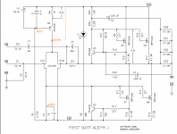
Tell me the points for measuring parameters for an accurate diagnosis. I will take measurements and show you.more info
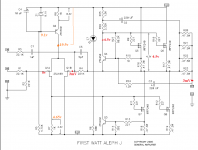
what you see on schmtc you already attached
measure DC offset also
show us pics , and check all solder points
measure DC offset also
show us pics , and check all solder points
I think I found the reason, the volume control potentiometer.and check all solder points
Attachments
On both channels, the quiescent current was set equal to cold 0.45 volts, when heated, the voltage dropped to 0.4 volts. This is normal? Supply voltage without load 25.5 volts under load 23 volts.is OK
Yes, on the resistors, the 0.47th output transistor at a temperature of ~ 70 * C, a voltage of 0.4 volts. That sounds very good.dc offset?
Thanks to Mr. Pass
 , simplicity is the key to reliability and quality
The bias voltage and the quiescent current on both channels are the same, but the gain on one channel is slightly less, the question is how to combine them to get the same signal level?everything OK
Attachments
The bias voltage and the quiescent current on both channels are the same, but the gain on one channel is slightly less, the question is how to combine them to get the same signal level?
As far as I can tell from your video, the DVM was set to read DC voltage across the speaker terminals. How is this going to tell you anything about the gain (AC!) of your amp?
You'd need to hook up your amp such that both channels get the same input (I'd suggest a 100 mV sine at 100 Hz or so) and then read the AC voltages across the speaker terminals of both channels in order to learn something about the gain balance of the two channels.
The video shows the voltage offset at the output of the amplifier.As far as I can tell from your video, the DVM was set to read DC voltage across the speaker terminals.
The difference in gain on each channel is audible even without measurements. The question was what is regulated, how can I level both channels, ok?
One Chanel no sound
Hello my aleph J one Chanel is no sound .
Basic is .47 MV and DC cannot set (-0000.00)
Pls tell me what can I do now ?
Best regards
Myint
Hello my aleph J one Chanel is no sound .
Basic is .47 MV and DC cannot set (-0000.00)
Pls tell me what can I do now ?
Best regards
Myint
The video shows the voltage offset at the output of the amplifier.
The difference in gain on each channel is audible even without measurements. The question was what is regulated, how can I level both channels, ok?
if you have genuine JFets in input ( BL range) , if all resistors are the same ,there is no reason that channels are having different gain
check all resistors , if there is no doubt in JFets
Hello my aleph J one Chanel is no sound .
Basic is .47 MV and DC cannot set (-0000.00)
Pls tell me what can I do now ?
Best regards
Myint
pics
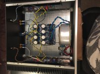
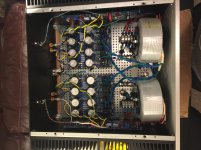
I got the Aleph J updated to dual-mono. 😀 Thanks to everyone for the advice, particularly ZM and @TungstenAudio. ZM, I'll get the fuses put into the SissySIT next.
It's getting back up to operating temp in the main system, but everything checked out wonderfully with the test rig.
Before and After...
It's getting back up to operating temp in the main system, but everything checked out wonderfully with the test rig.
Before and After...
Attachments
- Home
- Amplifiers
- Pass Labs
- Aleph J illustrated build guide