Tungsten Audio and ZM - Thanks!
All - A few questions, please.
1) I've been looking around re: PSU layouts in general. I've seen a few builds (including TAs in post #3796) that have what look to be ferrite chokes on the mains lines coming off the IEC. I've looked around re: their purpose (I assume to help reduce some mains hum), but I cannot find a confirmation re: a properly spec'ed part. If anyone happens to have a Mouser part number that they're willing to share for US 120V 60Hz, I'd be grateful.
2) I'm learning more and more, but if someone could confirm (or tell me I'm wrong) that even though the added transformer and PSU are capable of delivering more current, the amp sections themselves won't draw more current. So, there is no need to change fuses, correct?
3) Re: Grounding (Safety, Audio, Transformer shield). Both the M2x and Aleph J were/are for all intents and purposes silent with my ears to to the speaker driver using my current PSU. I get great imaging and that "black background" so often revered by us audiophools. So, I don't want to bugger something up. Given that hum is an oft discussed topic tied to ground loops... there are a few things I could use help with re: grounding, please.
It seems more straight forward than I originally expected, but just as soon as I think I actually understand something... 😀
With thanks!
PS - I can't stop listening to this amp in my system! I am now (semi)confident that it's not confirmation bias. One of the most uncanny things to me is its ability to make gorgeous music at far less than my normal listening volumes. All other amps I've used with the exception of a set of tube monoblocks don't seem to "come into their own" until the volume is higher. This amp makes beautiful music at whisper quiet volumes, gets louder when you need it, and it stays dead even on the way up. There's no "happy spot" in the volume. They're all happy spots. 😀 The consistency in its delivery from low volumes through loud enough to rattle the windows makes this amp a great fit for my system. It may just be that it works well with my speakers, but something is definitely afoot at the Circle K.
I'm curious if anyone else has a similar impression or could help me understand if there is a "why" behind how it does what it does.
All - A few questions, please.
1) I've been looking around re: PSU layouts in general. I've seen a few builds (including TAs in post #3796) that have what look to be ferrite chokes on the mains lines coming off the IEC. I've looked around re: their purpose (I assume to help reduce some mains hum), but I cannot find a confirmation re: a properly spec'ed part. If anyone happens to have a Mouser part number that they're willing to share for US 120V 60Hz, I'd be grateful.
2) I'm learning more and more, but if someone could confirm (or tell me I'm wrong) that even though the added transformer and PSU are capable of delivering more current, the amp sections themselves won't draw more current. So, there is no need to change fuses, correct?
3) Re: Grounding (Safety, Audio, Transformer shield). Both the M2x and Aleph J were/are for all intents and purposes silent with my ears to to the speaker driver using my current PSU. I get great imaging and that "black background" so often revered by us audiophools. So, I don't want to bugger something up. Given that hum is an oft discussed topic tied to ground loops... there are a few things I could use help with re: grounding, please.
- Safety and tying to thermistor. I could not see in pics or a layout how this should potentially be done. Today, I have the safety ground going straight to the chassis, with the CL-60 off of that to the PSU ground per the schematic. Should I try to figure out a way for the 2nd PSU and its thermistor to tie to the same point on the chassis? i.e. keep the exact same grounding point?
- Transformer shield. Currently, this goes to the same point on the chassis as my safety ground / CL-60. Should it also for the 2nd transformer?
- Audio Ground (neg speaker terminal). Today, I'm grounding the neg terminal to the PSU ground. It seems obvious (I hope), but the channels would now be separated, so each neg speaker terminal would now go to its associated PSU, correct.
Anything else that I may have missed?- Transformer shield. Currently, this goes to the same point on the chassis as my safety ground / CL-60. Should it also for the 2nd transformer?
- Audio Ground (neg speaker terminal). Today, I'm grounding the neg terminal to the PSU ground. It seems obvious (I hope), but the channels would now be separated, so each neg speaker terminal would now go to its associated PSU, correct.
It seems more straight forward than I originally expected, but just as soon as I think I actually understand something... 😀
With thanks!
PS - I can't stop listening to this amp in my system! I am now (semi)confident that it's not confirmation bias. One of the most uncanny things to me is its ability to make gorgeous music at far less than my normal listening volumes. All other amps I've used with the exception of a set of tube monoblocks don't seem to "come into their own" until the volume is higher. This amp makes beautiful music at whisper quiet volumes, gets louder when you need it, and it stays dead even on the way up. There's no "happy spot" in the volume. They're all happy spots. 😀 The consistency in its delivery from low volumes through loud enough to rattle the windows makes this amp a great fit for my system. It may just be that it works well with my speakers, but something is definitely afoot at the Circle K.
I'm curious if anyone else has a similar impression or could help me understand if there is a "why" behind how it does what it does.
Last edited:
@ItsAllInMyHead
1. bigger the better
2. same current consumption as with common PSU , simply because current consumption is set with parameters on channel pcbs - where you aren't changing anything....... but calculate separate fuses for each Donut ( usually VA/mains voltage , then fist bigger value , slow blow)
3.
- important thing for mains connected NTC is safe mounting - separate pcb or proper flameproof connector block, enough elevation from case etc.
one mains NTC per Donut ......... same as NTC connecting audio GND to case - one NTC per channel
-shield - connected to case on same screw where you connect safety gnd from IEC
-yup , each speaker neg terminal connected to own channel GND , be it on channel PSU pcb or on channel pcb , your choice - that's not so critical
as I said - chase pics of my builds ( my blog) and stare at goats ........
🙂
@ItsAllInMyHead
1. bigger the better
2. same current consumption as with common PSU , simply because current consumption is set with parameters on channel pcbs - where you aren't changing anything....... but calculate separate fuses for each Donut ( usually VA/mains voltage , then fist bigger value , slow blow)
3.
- important thing for mains connected NTC is safe mounting - separate pcb or proper flameproof connector block, enough elevation from case etc.
one mains NTC per Donut ......... same as NTC connecting audio GND to case - one NTC per channel
-shield - connected to case on same screw where you connect safety gnd from IEC
-yup , each speaker neg terminal connected to own channel GND , be it on channel PSU pcb or on channel pcb , your choice - that's not so critical
as I said - chase pics of my builds ( my blog) and stare at goats ........
🙂
Thanks, ZM!
1. I'll try to find something, but all the parts specify frequencies in the MHz range when I look at spec sheets. Admittedly, I'm confused. I've never used one.
2. Thanks, ZM. The donuts will be identical AS-4218. So, did I potentially misunderstand that I'm not necessarily needing to set the fuses for the normal operation, but for the added inrush due to the additional PSU. So, I need bigger fuses?
3. Understood.
- Sorry if I was not clear. Should the NTC's meet at the same chassis point (with the safety ground) or is it OK if they're a few inches apart?
- noted with thanks!
- 😀
I looked at a buuuuuuunch of pics trying to find Waldo and the goats. I wanted to just be sure of a few things.
1. choose by physical size , for exact purpose fine data is irrelevant
2.fuses by VA of Donut ; say 250VA , in 115Vac area - 250/115=2A5 slow blow; go figure ; if that's not enough for surge with existing soft start (mains NTC) , use first bigger value
3.they can be few inches apart (meet points) , but clean praxis is meeting all wires on one point of chassis
2.fuses by VA of Donut ; say 250VA , in 115Vac area - 250/115=2A5 slow blow; go figure ; if that's not enough for surge with existing soft start (mains NTC) , use first bigger value
3.they can be few inches apart (meet points) , but clean praxis is meeting all wires on one point of chassis
1. choose by physical size , for exact purpose fine data is irrelevant
2.fuses by VA of Donut ; say 250VA , in 115Vac area - 250/115=2A5 slow blow; go figure ; if that's not enough for surge with existing soft start (mains NTC) , use first bigger value
3.they can be few inches apart (meet points) , but clean praxis is meeting all wires on one point of chassis
1. Noted with thanks. It was interesting to read a few articles that were well above my feeble mind to try and understand how they work.
2. Thank you. All confirmed and understood with thanks. This is what I was thinking. I should have shown my math.
3. When new donuts arrive I can lay out chassis, but I am sure I can get them all to meet at same point cleanly.
I use ferrite chokes on the incoming AC power leads to filter out RFI present on the mains. How much good this does is difficult to quantify, but I have seen the effectiveness of ferrite chokes on computer equipment at FCC compliance test sites, so I know they do their job. My reasoning is to reduce as much line interference as soon as possible once the power enters the chassis. RFI has a nasty way of getting both inductively and capacitively coupled into secondary circuits. That's a fancy way of saying that I sleep better with ferrite filters on my AC lines. I get mine from my local electronics surplus store.
I'm using a pair of Antek AS-3220 toroids in my Aleph J. Separate AC line fuses are 1.6A, but 2A or even 2.5A would be fine as well. I prefer the CL-70 thermistors for inrush current limiting. They have a higher intial resistance and reach minimum resistance at a lower current than the more commonly used CL-60. Each power transformer has its own input terminal strip for the thermistors and 4n7 filter cap across the primaries.
The input safety ground is best tied to the chassis using a short wire with no other connections. The audio ground connection, through 10 Ohm resistors or thermistors may be made a few inches away from the safety ground. I do tie the audio grounds to chassis at the same point. The Antek electrostatic shield grounds (purple) may be tied to the chassis pretty much anywhere that is convenient. I just tie them at the same point for a dual-mono supply. At this point, the chassis is being used for what we call a low current density shield. I'm still amazed at how many open chassis (or no-chassis) builds I see out there. With all the electronic garbage in homes these days a good chassis shield is necessary insurance. Yes, RFI can be de-modulated down into the audio frequency range through the variety of non-linear elements in our amplifiers.
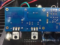
I’ve replaced Q4 with a new ZTX450, reflowed all the joints and not fixed unfortunately. Still -8.7v at the outputs..
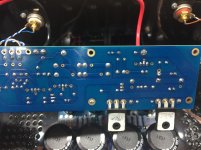
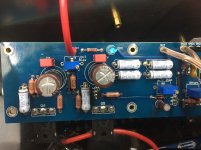
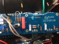
Here are a couple of photos of the bottom of the board. Can anyone see anything that appears wrong?
Here are a couple of photos of the bottom of the board. Can anyone see anything that appears wrong?
Attachments
I’ve replaced Q4 with a new ZTX450, reflowed all the joints and not fixed unfortunately. Still -8.7v at the outputs..
Here are a couple of photos of the bottom of the board. Can anyone see anything that appears wrong?
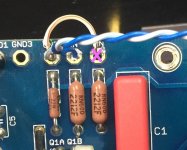
Might be a trick of the light but the middle leg of the FET marked 3980 looks a bit light on for solder to me. I can't see anything obviously dodge elsewhere. One for more experienced eyes? Let's see what other feedback you get.
Swap the JFET's between a good working board and a faulty board... and see if the fault follows the JFET's you removed from the faulty board
The middle pins of several of the MOSFETs appear a bit light, but I imagine they're well-flowed on the other side?
The power connection is also dodgy: note that many of the wire strands are not wetted.
I doubt either of those is your problem, though....
The power connection is also dodgy: note that many of the wire strands are not wetted.
I doubt either of those is your problem, though....
A fair observation on the mosfet soldering. Soldered the mosfets from the front side only. Any reason to do both sides?
Last edited:
Desoldering is my arch nemesis... I’m very concerned about desoldering and swapping the JFETs given that I’m unable to find any replacement LSJ74 B JFETs for sale.. The B’s appear to be unobtanium..
Does anyone know where I can buy a pair of matched LSJ74B JFETs or some equivalents that’ll do the same job?
A fair observation on the mosfet soldering. Soldered the mosfets from the front side only. Any reason to do both sides?
No reason to do both sides, but it's good practice to get in the habit of applying enough heat to the one side until you see the solder pull through to the other side.
Did you reflow the red power-wire connection?
Do you have a solder pump for de-soldering? They really are the bees knees.
I get my SJ74's from John LaGrue (punkydawgs on ebay) [1]. Toshiba's 'BL' grade matches with Linear System's 'B'. (Well, really the other way around, as Toshiba is the original manufacturer.)
[1] https://www.ebay.com/str/punkydawgs?_trksid=p2047675.l2563
You can practice desoldering using this tool: The Original Deluxe SOLDAPULLT: EDSYN Inc.
ALWAY use the Anti Static Wrist Strap | Jaycar Electronics when handling JFETs. Try not to touch the pins. Once they are soldered on a PCB, it is safe to touch the pins.
Check the soldering at the point "X" (attached)
ALWAY use the Anti Static Wrist Strap | Jaycar Electronics when handling JFETs. Try not to touch the pins. Once they are soldered on a PCB, it is safe to touch the pins.
Check the soldering at the point "X" (attached)
Attachments
- Home
- Amplifiers
- Pass Labs
- Aleph J illustrated build guide