
ItsAllInMyHead,
Are those 300 or 400 VA transformers?
400VA. Antek AS-4218. I had the original from the standard build, so I matched it. Probably not necessary, but they fit 😀.
I got the Aleph J updated to dual-mono. 😀 Thanks to everyone for the advice, particularly ZM and @TungstenAudio. ZM, I'll get the fuses put into the SissySIT next.
It's getting back up to operating temp in the main system, but everything checked out wonderfully with the test rig.
Before and After...
Dual mono and Sissies rule!
A couple of things caught my eye.
I did not see any thermistors between the PS grounds and the chassis. Are they hidden under the PS boards? The thermistors heat up and any heat under the PS boards and capacitors are unwelcome. There is also the danger of possible shorting of the power supply.
I noticed that the grounds of the positive and negative rails on the PS board are not joined at the PS board output. I can see that on the right channel board, not sure whether they are joined on the left channel board. You have separate positive and negative rail grounds going to the amplifier boards, joining at the amplifier board. However, the speaker negative is coming off the negative rail ground at the PS board output and the power supply ground to chassis is coming off the positive rail ground at the PS board output, which are not joined together (on right channel, left channel has speaker and chassis connection to negative rail ground). The PS board grounds are joined at the PS board input. So you have multiple ground points, which can cause noise issues.
Usually the grounds are joined together on the PS board at both ends, and then the V+, V-, and G are taken together to the amplifier board along with the ground to chassis from the PS board output. Some people connect the speaker negative to the amplifier board and some connect it to the PS board ground.
Are you hearing any hum?
Hi Roo2,
Any news on your AJ build?
Dennis
Hi Dennis. No luck yet. I replaced Q3 with no improvement. I’ve set it aside until I can find a pair of JFETs to buy, try. The Diyaudio store will get some in soon hopefully.
Ben & IAIMH,
Remember that if thermistors are used to make a ~10 Ohm connection between audio Gnd and chassis Gnd, then they will normally conduct very little current and stay cool. So if these thermistors are hiding under the PSU boards, they're Ok where they are. They will only get hot under a fault condition, in which case the AC line fuse is expected to blow.
Remember that if thermistors are used to make a ~10 Ohm connection between audio Gnd and chassis Gnd, then they will normally conduct very little current and stay cool. So if these thermistors are hiding under the PSU boards, they're Ok where they are. They will only get hot under a fault condition, in which case the AC line fuse is expected to blow.
Yes, you are correct - a brain fart on my part. 😱
They are not hot under normal operating conditions, unlike the thermistors in series with the transformer primaries.
They are not hot under normal operating conditions, unlike the thermistors in series with the transformer primaries.
Hi Dennis. No luck yet. I replaced Q3 with no improvement. I’ve set it aside until I can find a pair of JFETs to buy, try. The Diyaudio store will get some in soon hopefully.
I've invested in this bit of kit:
T4020 Anti-Static Mat 55 x 30cm - Altronics
in preparation for the next time I work with unobtanium transistors.
A moment of stray static doesn't add up to fun times.
....then they will normally conduct very little current ........
none current, practically
they're here just in case ...... which probably would never happen
Hi Dennis. No luck yet. I replaced Q3 with no improvement. I’ve set it aside until I can find a pair of JFETs to buy, try. The Diyaudio store will get some in soon hopefully.
Hi Roo2,
Looks like you can buy a single pair of replacement jfets now:
Linear Systems Matched JFETs – diyAudio Store
Cheers,
Dennis
I got the Aleph J updated to dual-mono. 😀 Thanks to everyone for the advice, particularly ZM and @TungstenAudio. ZM, I'll get the fuses put into the SissySIT next.
It's getting back up to operating temp in the main system, but everything checked out wonderfully with the test rig.
Before and After...
Looks very nice.
I have a few questions...
Tell us about the sound improvement...?? was it worth the effort??
- is that DELUXE 5U case?
- are the transformers 400VA?
- which L brackets did you use to mount the transformers? readily available off the shelf product??
Looks very nice.
Tell us about the sound improvement...?? was it worth the effort??
-
Unless the setups were tested using blind switching the impressions of before and after remain just that.
Major screw ups on the single power source setup should be done in order to be fixed by a double mono power supply approach.
But improvement, other than peace of mind and a nice looking build only those that really compared identical builds can reveal and backup with test data and graphs.
I suspect Master Papa Nelson, Zen Mod and many more that actually have the upper mentioned setup on bench should or were able to proper test and measure.
Needless to say i would be really eager see dissected this mystery creature : "the dual mono power supply "
And highlighted why a builder should need to go this way if in the search of a closer to ideal audio signal reproduction other than "I prefer it or I always do it or That's the way to go".
My rant went long but basically I consider (and yet remain open minded) , as an engineer, that without verifiable data or comparative test done, there is no perceptible audio difference between the two power supply approaches.<Or is it?>
The power supply behavior is directly influenced by the load... but how much and how big is the influence and what are the parameters that make the dual approach a must or capable of bringing detectable differences.
As minimum suspects like very much transformer power reserve; great filters, immense capacitor banks with low esr, beefy transport cables as close to ideal current paths seem to be satisfied almost always in this community 😀.
Last edited:
Dual mono and Sissies rule!
A couple of things caught my eye.
I did not see any thermistors between the PS grounds and the chassis. Are they hidden under the PS boards? The thermistors heat up and any heat under the PS boards and capacitors are unwelcome. There is also the danger of possible shorting of the power supply.
I noticed that the grounds of the positive and negative rails on the PS board are not joined at the PS board output. I can see that on the right channel board, not sure whether they are joined on the left channel board. You have separate positive and negative rail grounds going to the amplifier boards, joining at the amplifier board. However, the speaker negative is coming off the negative rail ground at the PS board output and the power supply ground to chassis is coming off the positive rail ground at the PS board output, which are not joined together (on right channel, left channel has speaker and chassis connection to negative rail ground). The PS board grounds are joined at the PS board input. So you have multiple ground points, which can cause noise issues.
Usually the grounds are joined together on the PS board at both ends, and then the V+, V-, and G are taken together to the amplifier board along with the ground to chassis from the PS board output. Some people connect the speaker negative to the amplifier board and some connect it to the PS board ground.
Are you hearing any hum?
Ben & IAIMH,
Remember that if thermistors are used to make a ~10 Ohm connection between audio Gnd and chassis Gnd, then they will normally conduct very little current and stay cool. So if these thermistors are hiding under the PSU boards, they're Ok where they are. They will only get hot under a fault condition, in which case the AC line fuse is expected to blow.
Yes, you are correct - a brain fart on my part. 😱
They are not hot under normal operating conditions, unlike the thermistors in series with the transformer primaries.
@Ben Mah and @TungstenAudio. Thank you. I learned a lot re: the thermistors. Yes, the thermistors are tucked up under the PSU boards. They're heat-shrinked also just in case. l appreciate the concern and the follow up explanation that I should be okay. My brain farts will run the dog out of the room, so no worries...

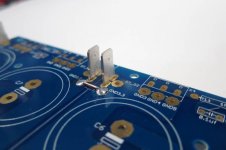
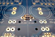
@Ben Mah - I appreciate the overview re: the grounding plan. I want to be sure I grasp your potential concern and address it if necessary. Please correct me if I am wrong. I think I am okay because the grounds associated with V+ and V- on the DIYAudio PSU boards in my build are joined by the jumpers that run between the two "halves". Also on the AC / rectification side, there is a jumper. See pic. (Credit for pics to Jim, I borrowed his from the build guide). Is this sufficient? From a measurement standpoint, there is 0R between the ground posts on the Euroblocks closest to V+ and the one closest to V-. I think for all intents and purposes they're the "same" ground. Or... am I mistaken and are you meaning that I should have a tie between the left and right channel PSU board grounds? At this time, the only commonality between the left and right PSU is that both thermistors run to the chassis ground.
Neither the SissySIT or the Aleph J have any hum at all with my ear to the drivers. So perhaps I got lucky????
Looks very nice.
I have a few questions...
Tell us about the sound improvement...?? was it worth the effort??
- is that DELUXE 5U case?
- are the transformers 400VA?
- which L brackets did you use to mount the transformers? readily available off the shelf product??
Thank you!
re: sound changes. I am terrible at reviewing... so - add a pile of salt vs. a grain. It's early yet, and for me confirmation bias is a real thing. With all the caveats and qualifiers out of the way...
The soundstaging and what I think is often called placement has improved. The (my own word) "sharpness" and clarity of where something is in space is better. Background instruments or backing vocals seem to emerge a bit from the ... background... LOL! They don't get lost in the mix. I can almost be sure of that characteristic. Was it phenomenal before, yes. Was it a "dramatic" improvement, no. To me, it was worth it.
I wanted to get an identical set of two PSU/chassis combos built to the best of my abilities so I could swap boards and blind A/B amps. Monoblocks were out of the question for space considerations, so this was my attempt to give amps the best power I could for comparisons. As side benefits, I learned a lot, and I enjoyed the building process. I still hate the chassis work though... 😀
Yes, Deluxe 5U case.
Antek AS-4218 transformers
The slightly larger version of this. https://www.lowes.com/pd/National-H...n-x-3-98-in-Zinc-plated-Flat-Brace/1000349847
In hindsight, I'd like something a bit wider and with an inch or more more space between the last hole and the end of the bracket, but they work well.
Attachments
Last edited:
Unless the setups were tested using blind switching the impressions of before and after remain just that.
+1
I couldn't add your quote to the previous post for some reason.
Thanks for that, very nice and concise.
If I may add, the obvious improvements in sound quality may become apparent after a few weeks of listening to the amp as a background music source. You should be able to form a much better opinion with a greater amount of certainty, about what improved in sound reproduction. A/B usually gives false impressions; what sounds great today, may sound tiring tomorrow and in particular, a week later. The opposite can happen as well....
If I may add, the obvious improvements in sound quality may become apparent after a few weeks of listening to the amp as a background music source. You should be able to form a much better opinion with a greater amount of certainty, about what improved in sound reproduction. A/B usually gives false impressions; what sounds great today, may sound tiring tomorrow and in particular, a week later. The opposite can happen as well....
besides each channel having its own PSU , benefit is there also from doubled energy source/storage
is it worth ?
to me it is
regarding measurements - that would demand some sort of stereo measurements , involving brain etc.
as our dear Sigfried used to say , when asked about did he believe in double blind testing - "I believe in long term testing"
so , I'm saying that I prefer dual mono ; if that itch someone enough to check - be my guest
if not - why should I care ?
regular THD , IMD , whatever testing will reveal difference in one channel vs. two channel driven , while observing just one channel output
is it of consequence at power levels one is using is completely arbitrary .....
Nelson switched from a stereo PSU to a de-coupled stereo PSU with the F7.
Was it because he could hear the difference, or only because he had run out of the old PSU boards and decided to do something different?
Was it because he could hear the difference, or only because he had run out of the old PSU boards and decided to do something different?
@Ben Mah - I appreciate the overview re: the grounding plan. I want to be sure I grasp your potential concern and address it if necessary. Please correct me if I am wrong. I think I am okay because the grounds associated with V+ and V- on the DIYAudio PSU boards in my build are joined by the jumpers that run between the two "halves". Also on the AC / rectification side, there is a jumper. See pic. (Credit for pics to Jim, I borrowed his from the build guide). Is this sufficient? From a measurement standpoint, there is 0R between the ground posts on the Euroblocks closest to V+ and the one closest to V-. I think for all intents and purposes they're the "same" ground. Or... am I mistaken and are you meaning that I should have a tie between the left and right channel PSU board grounds? At this time, the only commonality between the leftno and right PSU is that both thermistors run to the chassis ground.
Neither the SissySIT or the Aleph J have any hum at all with my ear to the drivers. So perhaps I got lucky????
It was this picture that caught my attention:
https://www.diyaudio.com/forums/att...42-aleph-illustrated-build-guide-img_1531-jpg
On the right channel PS board it appears to me that at the PS board output (left side of board), the two sides of ground are not tied together. The three solder pads with wire holes are empty and not soldered, and there are individual positive and negative rail ground wires connecting to the amplifier boards.
Edit:
It looks like the capacitors are blocking the view of the wire connecting the two grounds at the PS board output. Looking extra hard I think I see a bit of solder. In that case you do have the two sides of ground connected at the board output - my mistake for not seeing that.😱
For a more robust connection of the two sides of ground the three unused pads can also be used to tie the two sides together.
Those unused pads are actually a better place to connect the ground to the amplifier board, speaker, and to the chassis. It is better for grounding if the ground connection to the capacitors of a dual rail supply is located equally between the positive and negative rail grounds.
Last edited:
- Home
- Amplifiers
- Pass Labs
- Aleph J illustrated build guide