Hi,
I just finished the amplifier. Everything works fine. I still have a dumb question: in the conditions where I have no hum or noise, the power is 30W without limiting, what can be the differences if I replace the two transistors 2SJ271 with two SJ74 matched and originals?
I have +-28V, 1,1A/ch Bias, 0.01V offset
I use with XLR IN, the only thing not good is when I put IN- to GND for using RCA cable, the ampli start to have hum…
Thank’s
Attachments
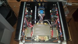
I can't hear difference between J271 and 2SJ74BL
hum with SE input , most probably wiring or magnetic field of that huge EI xformer
hum with SE input , most probably wiring or magnetic field of that huge EI xformer
Hi,
Just wondering, are there distortion measurements available for the Aleph J under load?
This is what I get:
Load is a power resistor of 8 ohm.
R24 (dynamic CCS feedback) 950 ohm for 50% ratio.
DC bias is 450mV/0.47R approx. 1A/fet
2 1nF caps installed (helped THD a bit, but circuit was not oscillating)
Clipping at 15.5V RMS (30W)
Measurements at 14V RMS (24W)
100Hz 0.056 THD
500Hz 0.25 THD
1KHz 0.38 THD
10KHz 4% THD !
20KHz 8% THD !
The pcb area around base Q4/R27/R15/R24 is quite sensitive. So moving the extra 1nF cap to a physical other place might help?
Do I have to hunt after a problem or are these figures normal?
Thanks!
Big question...how and where insert a potentiometer for volume control. Thanks for the answers
in front , where else ?
if you try to put it between amp and speaker , it'll act funny , at least for some time

if you try to put it between amp and speaker , it'll act funny , at least for some time
After looking at the picture I submitted and noticing the same thing you did, I filled the pads with solder on the back, the fronts were all full.
Also drew the solder up the mosfet legs as best I could.
Using good old Kester 44, I just didn't put all the solder on those mosfet pads that could be put.
I'm going to follow your advice and get some magnification to use for inspecting solder joints. At work there used to be some dandy 4" diameter ones mounted on a flex arm that I think is what I need, so off to Google in search of same.
Where are you with AlephJ? Hope you don't give up, it's too good of amp to throw in the towel!
Russellc
Where are you with AlephJ? Hope you don't give up, it's too good of amp to throw in the towel!
Russellc
Got some Q2,3,4 replacements from Mouser for some trial by elimination troubleshooting, which is my next step.
Also had to get some more Keratherm from the diyAudio store. I boogered up a couple of pads (some of the rubbery stuff peeled off) with all the in/out of board #1.
Haven't quit, just have not had time to pay proper attention to working on it.
in front , where else ?
if you try to put it between amp and speaker , it'll act funny , at least for some time
You crack me up, man.
ook that
I'll send you Babelfish J , two complete functional channels , pulled from amp when I rework it as Babelfish M25
even mosfets are there , on short wires
I'll send you Babelfish J , two complete functional channels , pulled from amp when I rework it as Babelfish M25
even mosfets are there , on short wires
ook that
I'll send you Babelfish J , two complete functional channels , pulled from amp when I rework it as Babelfish M25
even mosfets are there , on short wires
Goofball audio electronics wizard with a heart of gold, you are.
Goofball audio electronics wizard with a heart of gold, you are.
So long as I'm at it; 6L6 and MJ to name 2 of a few should be recognized (maybe sans the goofball appellation, though they both have their moments)
as well.
This community in general has really good folks in it.
As has been said in Arkansas at such times; "Y'all are awright by me."
I don't think its that easy, is it? That's why there are Buffers and Preamps that do this but keeping impedances in the 'correct' realm.Nice answer...but seriously? Where? after the first resistors r1, r3 with a T circuit?
A power amp just does it's thing, no volume control. Perhaps for testing purposes, but not for a final solution.
I know nothing about this though. Maybe it is as easy.
Yes, it is that easy. 
Potentiometer is placed in front of amplifier input, amplifier input now takes signal from potentiometer wiper.
Potentiometer is nothing more than a voltage divider.
Potentiometer is placed in front of amplifier input, amplifier input now takes signal from potentiometer wiper.
Potentiometer is nothing more than a voltage divider.
Last edited:
Yes, it is that easy.
Attachments
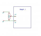
Thanks Itsmee for the answer..but the problem is that the amplifier has an balanced input...so I suppose I cannot reduce the voltage of the + line only...
Same answer still applies.
Big question...how and where insert a potentiometer for volume control. Thanks for the answers
In front. After dealing with the surprise unstated detail that the amp has balanced inputs, you can deal with the surprise unstated detail that the potentiometer has 4 gangs. Two for the left channel (+ side and - side), two more for the right channel (+ side and - side).
Here is one example
9mm ALPS A50K 50K Audio Taper Potentiometer 15mm Knurled Shaft 4 Gang-in Potentiometers from Electronic Components & Supplies on Aliexpress.com | Alibaba Group
I am thinking about monoblocks and saving money on chassis and power supplies. Would someone tell me if the following would not work, or otherwise be a bad idea? I am a liberal arts guy, not an engineer, so please be gentle.
I have an Aleph J and an M2, each in a Deluxe 4U DIY Audio Store chassis, and both with very similar power supplies (maybe the brand of capacitors are different). If I wanted to convert them to monoblocks without buying extra chassis and power supplies, could I set up the two chassis so that each has an M2 board and an Aleph J board, then install a heavy duty 3PDT toggle switch so that the power supply would only power one board at any given time?
Thanks
I am thinking about monoblocks and saving money on chassis and power supplies. Would someone tell me if the following would not work, or otherwise be a bad idea? I am a liberal arts guy, not an engineer, so please be gentle.
I have an Aleph J and an M2, each in a Deluxe 4U DIY Audio Store chassis, and both with very similar power supplies (maybe the brand of capacitors are different). If I wanted to convert them to monoblocks without buying extra chassis and power supplies, could I set up the two chassis so that each has an M2 board and an Aleph J board, then install a heavy duty 3PDT toggle switch so that the power supply would only power one board at any given time?
Thanks
Long ways from an audio electronics guru myself, but that sounds like a capital idea to me.
Have you got room on the back panel for the additional input and output connectors?
- Home
- Amplifiers
- Pass Labs
- Aleph J illustrated build guide