DC offset = 0 volts both channels
Bias set to 400mv runs stable
Heatsink temp 109°
Output mosfets 119°
Bias set to 400mv runs stable
Heatsink temp 109°
Output mosfets 119°
Are you connecting the Emotiva with the RCA outs or the headphone jack?
What have you been plugging the phonostage into before the Aleph?
What have you been plugging the phonostage into before the Aleph?
I typically hook my turntable into the phono stage then into the aux in on the emotiva which until today was hooked up to an adcom gfa 5500.
I tried hooking the Aleph J in place of the adcom(using the rca jacks). Very loud buzzing I didn't try playing music.
After I tried running the phonostage directly into the aleph J. loud humm. i did play some music but the volume was very loud.
just now I tried hooking into the headphone jack of the emotiva with the same bad buzzing/hum results...
maybe I have a ground issue?
A new Aleph J was born into the DIY world today! I set the bias and dc offset as described by 6L6 at the begining of this thread and it sounds great when i drive it with my laptop. Currently Nina Simone is filling our Saturday morning with lots of smiles.
Congratulations! Enjoy the music, it’s a great amp
What a difference two little jumpers make! Somehow I missed that the input - has to be shorted to ground when the input is single ended (RCA jaack input). But some long looks at 6L6's COMPREHENSIVE build guide and I saw some thing that looked different.
Thanks for all your help Jim!!
I am now enjoying the sweet sounds of vinyl and suddenly my collection sounds new🙂
Thanks for all your help Jim!!
I am now enjoying the sweet sounds of vinyl and suddenly my collection sounds new🙂
Attachments


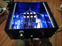
Couldn't help myself... Just had tp hook the new beast up to the, mostly finished, NuTube preamps I'm side by side building.
The result is pretty amazing! I didn't think the sound would change so dramatically. After moving the bias on the NuTubes down to 10.0volts (formerly set at 10.5volts) the sound is surpriingly both more clear and warmer. A very pleasing combination. Vocals have a realistic presence that's almost hard to believe i find myself looking around the room grinning in disbelief.
The NuTube is not without it's drawbacks. The microphonic ring is at a particularly cruel fequency and not easy to get rid of. And the circuit could benefit from some cleaner power, maybe it's destin for batteries?
So far, however, I can find no flaws in the Aleph J's sound. the resolution at the high and low end is just stunning. The sound is relaxed and natural when playing Johnny Cash American recordings you'd swear he's in the room. afterwards I put on Nine inch Nails the Fragile and I was surprisethat there was still paint on wall when it finished playing. The guitar was as forceful as a live show without sacrificing the other layers of complicated sounds.
I think it's gonna be a long night...
Attachments

Hi guys! Stupid question...I've mounted two PCBs and for one no problem in the setting of bias and offset. For the other now way of setting it. I move all pots but just little variations can be seen (i.e. I have 22 V on that output jack and moving both offset and bias pots I cannot modulate this value. DC volts between source resistor is always 0). Do not know where I can start checking....
Assuming you have properly stuffed the PCB and have all the smaller transistors in the proper spot and aligned correctly, you have a bad solder joint somewhere.
Poke and move and flex the PCB a little with the meters hooked up and see if you can see a change, and if you do resolder there. If no change, reflow everything.
Poke and move and flex the PCB a little with the meters hooked up and see if you can see a change, and if you do resolder there. If no change, reflow everything.
MOSFET Q5/Q6/Q7/Q8 Matching/Stuffing
Apologies for asking a question that's been asked before but I'm seeking clarification around the matching of the MOSFETs and making sure I get them stuffed in the board in the right spots. I've done enough desoldering to know that it's best avoided, so that's what's driving my query.
I get that the message from:
Aleph J illustrated build guide Post #680
Aleph J for Universal Mounting Spec Post #473
Aleph J for Universal Mounting Spec Post #392
is to match the Upper and Lower MOSFETs.
I take it that the terms "Upper" and "Lower" are referring to the position on the schematic because if you look at the PCB, the components all line up horizontally and there is no obvious upper / lower? If component IDs had been quoted in the above links, I wouldn't need to ask so I'm sure that those in the know will bear with me.
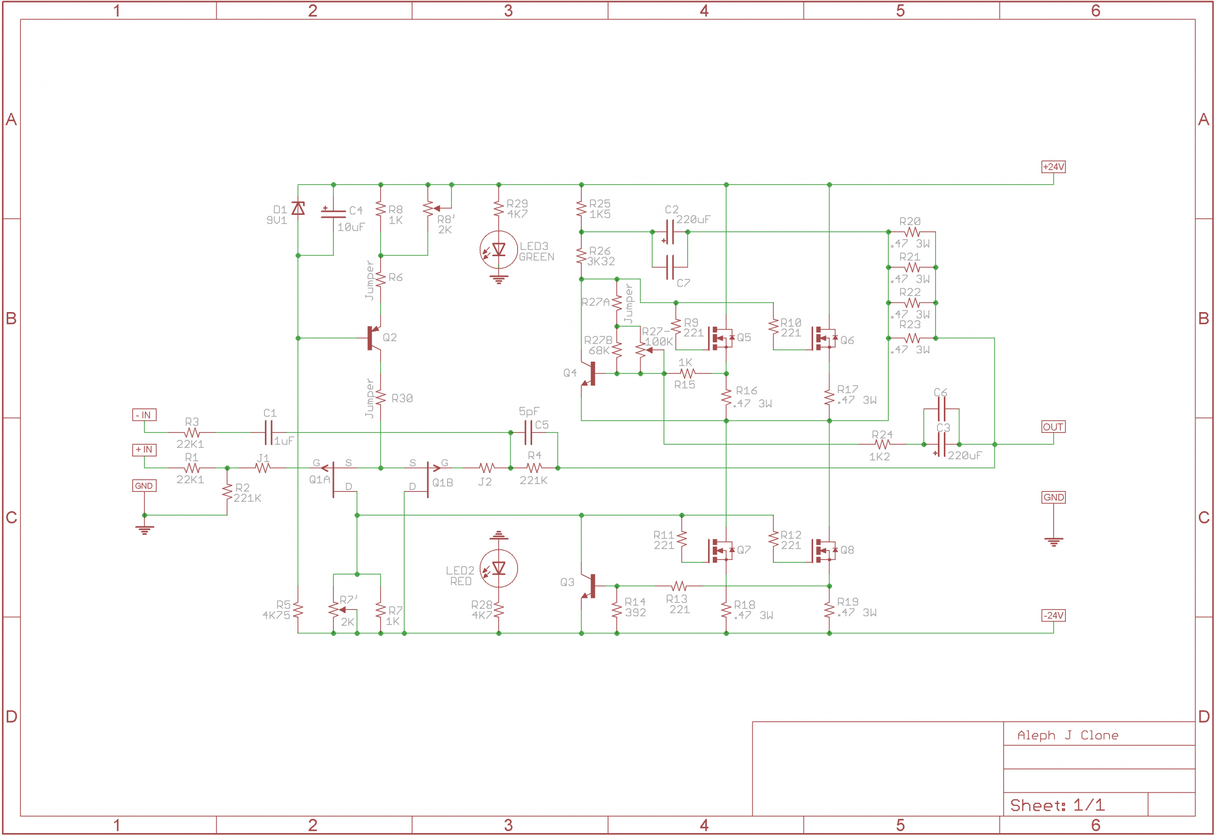
Please confirm for me that in terms of component numbers, we're talking about matching as follows:
http://www.firstwatt.com/pdf/art_mos_test.pdf
The topology around Q5/Q6 and Q7/Q8 appears to be aligned with Fig 3a.
If it's something else, please advise preferably with an explanation so that I can improve my understanding.
Thanks and
Apologies for asking a question that's been asked before but I'm seeking clarification around the matching of the MOSFETs and making sure I get them stuffed in the board in the right spots. I've done enough desoldering to know that it's best avoided, so that's what's driving my query.
I get that the message from:
Aleph J illustrated build guide Post #680
Aleph J for Universal Mounting Spec Post #473
Aleph J for Universal Mounting Spec Post #392
is to match the Upper and Lower MOSFETs.
I take it that the terms "Upper" and "Lower" are referring to the position on the schematic because if you look at the PCB, the components all line up horizontally and there is no obvious upper / lower? If component IDs had been quoted in the above links, I wouldn't need to ask so I'm sure that those in the know will bear with me.
Please confirm for me that in terms of component numbers, we're talking about matching as follows:
- Q5 and Q6
- Q7 and Q8
http://www.firstwatt.com/pdf/art_mos_test.pdf
The topology around Q5/Q6 and Q7/Q8 appears to be aligned with Fig 3a.
If it's something else, please advise preferably with an explanation so that I can improve my understanding.
Thanks and
Last edited:
Q5 and Q6
Q7 and Q8
Correct. 5&6 should be a pair, 7&8 should be a pair.
Correct. 5&6 should be a pair, 7&8 should be a pair.
Bravo and thanks for the quick reply.
5&6 are the transistors for the Constant Current Source, so they need to be matched so there's equal current though both, and one doesn't turn on a bit sooner and hog the current while the other just sits there.
7&8 are the output transistors. The same reasoning as above applies.
The pairs don't need to be matched to each other.
7&8 are the output transistors. The same reasoning as above applies.
The pairs don't need to be matched to each other.
You need to match Q5 to Q6, and separately Q7 to Q8.
Hope that helps.
Dennis
Edit: Jim answered already.
Hope that helps.
Dennis
Edit: Jim answered already.
That’s and odd mixup, the Aleph J transistor kit should only ever come with a 9.1v Zener.
The 5.1v and 6.1v selections are for an entirely different amplifier... the F6
Odd as this was... it happened again in the Aleph J transistor kit I bought.
I already had the correct 9.1v Zener from Mouser, but was scratching my head as to what the 5.1v and 6.1v were for?.. Now I know.
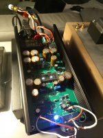
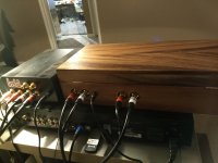
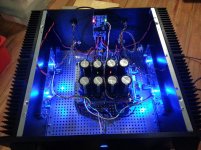
Not the tidiest wiring job ever but it's finally finished and most importantly it works. I'll do a tidy up in due course (maybe never?).
Thanks to Nelson, 6L6, didiet, diyAS and everyone else for their help along the way.
Got the big fella biased at 450 mV and the heat sinks are registering 43 - 45 °C. That's the advantage of the modushop 5U chassis.. 😉
Thanks to Nelson, 6L6, didiet, diyAS and everyone else for their help along the way.
Got the big fella biased at 450 mV and the heat sinks are registering 43 - 45 °C. That's the advantage of the modushop 5U chassis.. 😉
Attachments
Odd as this was... it happened again in the Aleph J transistor kit I bought.
I already had the correct 9.1v Zener from Mouser, but was scratching my head as to what the 5.1v and 6.1v were for?.. Now I know.
May I ask where did you bought such a kit?
May I ask where did you bought such a kit?
From the store:
The diyAudio Store - DIY amplifier kits, chassis, and parts
The Aleph J kit is sold out currently, as are the P channel JFETs. They don't have a long shelf life. Too much demand.
Not the tidiest wiring job ever but it's finally finished and most importantly it works. I'll do a tidy up in due course (maybe never?).
Thanks to Nelson, 6L6, didiet, diyAS and everyone else for their help along the way.
Got the big fella biased at 450 mV and the heat sinks are registering 43 - 45 °C. That's the advantage of the modushop 5U chassis.. 😉
Set the emissivity of my IR thermo-gun unit to a more sensible 0.85, so those temps are more 45 - 47 °C down the bottom of the heat sink. Just getting a quick audition (a bit hard with a 4yo - not me - in the house ) of the Aleph J with my main system (includes floor standing speakers with 92 dB/W/m) ... noice mate, noice ! 😉
For my winter project i'm planning to build an amplifier.
As pre i will use my Naim UnitiQute 2 (for now).
After a lot of reading i got my attention to the FirstWatt designs because my first requirements are - Pure Class A - Single Ended - Fets.
Finaly i think the Aleph-J will suits most of my requirements so i am planning to build one .. yeah!
I need a lot of reading as i see so many threads about this amp and the different 'settings'.
Planning is to build the Aleph-J according the following items:
- PCB v2
- BOM Rev. C for now .. i know there is a Rev. D but i need a lot of reading 🙂
- J74/J74 Stereo Differential Kit when available
- Aleph J Transistor Kit (i think the items are not complete .. zener?)
- Universal Power Supply
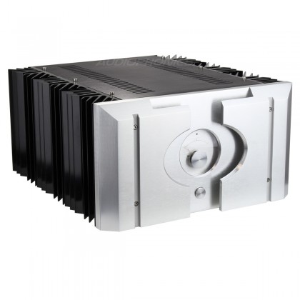
I hope these items and heat dissipation will fit into this chassis ?
To be continued ...
As pre i will use my Naim UnitiQute 2 (for now).
After a lot of reading i got my attention to the FirstWatt designs because my first requirements are - Pure Class A - Single Ended - Fets.
Finaly i think the Aleph-J will suits most of my requirements so i am planning to build one .. yeah!
I need a lot of reading as i see so many threads about this amp and the different 'settings'.
Planning is to build the Aleph-J according the following items:
- PCB v2
- BOM Rev. C for now .. i know there is a Rev. D but i need a lot of reading 🙂
- J74/J74 Stereo Differential Kit when available
- Aleph J Transistor Kit (i think the items are not complete .. zener?)
- Universal Power Supply
I hope these items and heat dissipation will fit into this chassis ?
To be continued ...
- Home
- Amplifiers
- Pass Labs
- Aleph J illustrated build guide