I would think so.So I can probably use both, one for each channel, as the specs are the same for both trannies.
Thanks to 6L6, ZM and all others for their great help in this and other threads.
I am finishing my Aleph J build and would like to know the current thinking on what to do with R8.
Is it best to set the 500R pot at 250R and leave it alone, or is it best to put in a 250R fixed resistor?
Thanks,
Matt
I am finishing my Aleph J build and would like to know the current thinking on what to do with R8.
Is it best to set the 500R pot at 250R and leave it alone, or is it best to put in a 250R fixed resistor?
Thanks,
Matt
Hi Matt,
I believe R8 is nominally set at 1K to give about 8.4mA through the jfets.
I used a 2K pot set at 1K before installation and never adjusted it. In retrospect,
I could have just used a 1K fixed resistor in its place. The offset was
nulled using the 2K pot at P7 and bias controlled by the R27 (100K) pot.
Hopefully others can chime in.
Cheers,
Dennis
Thanks, Dennis,
Sigh...somehow was working off of an older BOM and schematic and didnt catch the revision of R8 from 500R to 2K...
Best to do a little revision at R8 before finalizing the build.
I appreciate your help, Dennis!
Matt
Sigh...somehow was working off of an older BOM and schematic and didnt catch the revision of R8 from 500R to 2K...
Best to do a little revision at R8 before finalizing the build.
I appreciate your help, Dennis!
Matt
R8 - use 1K resistor.
The CCS current is mainly defined by the Zener value and the pot will only have minimal effect to effect it. If we ever do a revision to the PCB the ability to place a pot there will be eliminated. 🙂
The CCS current is mainly defined by the Zener value and the pot will only have minimal effect to effect it. If we ever do a revision to the PCB the ability to place a pot there will be eliminated. 🙂
Question regarding the power supply caps. If you wanted to use screw type caps (total of 4 @15k each)and with wire wound resistors, could you use a .235 resistor for a pair of caps in series to total .1175 for both resistors or would you use .1175 after the rectifier and wire accordingly? Guess you could do both but not 100% sure. Thanks for any suggestions one may have.
Looks like I cant edit my original comment but looking at post 1826; i'm wondering what the values are essentially for the resistors on the caps sinces there's two
Hi everybody,
I'am a very beginner in amplifier building and Aleph J is my first project.
Yesterday i finished my Aleph J with DIY Store parts (PSU, PCtheB, JFET).
I powered up amplifier and ... problems :
PSU LEDs where shinning, Amplifier Board LEDs 1 where shinning, but Amplifier Board LED 2 were OFF and dissipators remain cold and ...
Other problem, when i tried to adjust offset --> DC volts across the output jacks : 24 V ! and nothing appened when i adjusted R7 pots.
All there problems were the same on the two amplifier modules.
Any ideas about that ?
Thanks for your help
New Aleph J - Failed Bulb Test
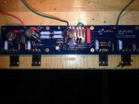
Greetings, I’m a first time poster and a novice. I’m working on my second build. My first was an F5 in 2014 (tuned out well). The Aleph J is my second. I finished populating the boards and on power up, both boards (individually) are failing the bulb test, and have very similar measurements. AlephJ and PSU Boards, Jfets, chassis, purchased from the DIYAudio store, everything else is new from Mouser.
Prior to power up
· Bulb Tested PSU alone in chassis. Transformer is an Antek 400 VA with dual 18V secondarys. Without Alephj boards connected, 26.2 V+ and -26.2 V- and bulb glows for a second and then goes out as expected.
· I measured each resistor before adding to boards using BOM ver D schematic
· Set R27 to 68k and placed jumper where needed
· Set R7 to 1k, and used 1k resistor for R8
Tests / Checks - one board
· Replace Q2, Q3, Q4 with BC556/546, no change, other than some slight changes in voltages above, Zetex passed diode test after removed as well
· Replaced Q1A and Q1B with another matched set of Lsj74B from DIY store, no change (new pair - 8.1 and 8.2 idss)
· I verified placement and re-tested resistors (in place) each values match schematic, r13/r14 shows correct parallel value as those two did not measure individually, and verified orientation of transistors and capacitors
· Checked for any shorts or bad solder, reflowed each part
· Tested mosfets to be sure not shorted to heatsinks, and powered up without boards attached to heatsink
Current Measurements (both channels near identical) - With both boards or single board connected – 60w blub glows steady, just a bit less than bright
· V+ (+7.9) and V- (-7.9)
· 4.2v across R27
· 4.4v across R7
· 5.0v across R8
· 2.9v across R6
· 7.0v across R5
· 0v on R1, R2, R3, R4, R9, R10, R11, R12 R20, R21, R22, R23
· 8.7v across D1 (R7 adjustments will cause value to change)
· .2v on R16, R17, R18, R19, R26
· .1v R25
· Q5 & Q6 – G to S = 4.3v, G to D = .3v, D to S = 4.6v
· Q7 & Q8 – G to S = 4.3v, G to D = 6.2v, D to S = 10.5v
· DC offset 2.4v
Observations for one board
· Adjusting R7 to lower DC offset - blub glows brighter as dc offset decreases. Lowest DC offset I can reach at pot limit is .3v with very bright bulb
· Adjusting R7 to increase DC offset, blub eventually go out right at limit of pot, but DC offset is now extremely high at 19+ v
· Mosfets are basically cold, Q7& Q8, maybe a just a little warm
The picture is before I switched Fairchild BJT. I ordered some spare mosfets and Zeners, but do not have them yet. I am thinking POTS, Mosfets, and Zener would be next in line to pull check, all seem like a long shot, something is just not adding up that I am missing.
Thanks in advance for any suggestions and insight offered.
-Donn
Attachments
I have been there, done that!
I have been there, done that!!
The bulb tester is only to be connected when you first start up the amplifier (or any other device that you want to test and suspect can be faulty). If you have faulty conections or there is a major error in one of your components it will show that something is fishy by lighting up abnormally and you have a chance to switch it off before something is burning, but after that..... disconnect it!😎
Since the filament is affected by the amount of current that you send through the bulb and therefore also change the resistance of the bulb (the quantity of light emitted) you have no use for it after the first check.
You will even have problem measuring anything in the amp with the bulb tester connected cause you will not get correct readings. Instead, if you start adjusting the current used by the amp, the bulb will counterwork that by higher resistance and burning brighter but you will end up with less in your amp so......
ONLY ON THE FIRST START UP!
You better connect a dummy load on the output, that will help you more.
You cannot set the bias with the bulb tester in place.
One makes this mistake only once, usually your first amp build. Ask me how I know. 😱
Thanks for the information and quick reply. I removed the bulb tester as advised and powered up. No problems.. Set bias and dc offset without any issues and it sounds very good. Will let it play for a while and retest.
Thanks again!
Thanks again!

The good thing about trying to set bias with the bulb tester is that you very likely will not do any damage to anything!
Let it warm up and check the offset again.
(And "warm up" in Aleph land really means "get darn near hot")
😀 😀 😀
Let it warm up and check the offset again.
(And "warm up" in Aleph land really means "get darn near hot")
😀 😀 😀
Start by posting some in-focus, well-lit photos. 🙂
I powered up amplifier and ... problems :
PSU LEDs where shinning, Amplifier Board LEDs 1 where shinning, but Amplifier Board LED 2 were OFF and dissipators remain cold and ...
Other problem, when i tried to adjust offset --> DC volts across the output jacks : 24 V ! and nothing appened when i adjusted R7 pots.
All there problems were the same on the two amplifier modules.
Any ideas about that ?
Thanks for the information and quick reply. I removed the bulb tester as advised and powered up. No problems.. Set bias and dc offset without any issues and it sounds very good. Will let it play for a while and retest.
Thanks again!
Good to hear; enjoy.
Hello guys;
Sorry to drop in kinda off topic; but a fan of this thread asked me to help with a one page version of your interesting thread the same as in Salas's Simplistic NJfet Riaa.
So here it goes a link for anybody who needs a one page version of the thread to quicly access and scroll and to avoid the uncomfortable " have you used search? " question 🙂
FULL Aleph J illustrated build guide
Hello guys;
Sorry to drop in kinda off topic; but a fan of this thread asked me to help with a one page version of your interesting thread the same as in Salas's Simplistic NJfet Riaa.
So here it goes a link for anybody who needs a one page version of the thread to quicly access and scroll and to avoid the uncomfortable " have you used search? " question 🙂
FULL Aleph J illustrated build guide
Thank you escucalin! Very helpful indeed! That will help alot of people including myself who is starting with the project or want to learn or keep a soft copy of the thread!
Best regards,
Tom
- Home
- Amplifiers
- Pass Labs
- Aleph J illustrated build guide