escucalin - Fantastic!! Thanks for making that available.
😀
Pleasure to be of help; Every one here brings a bit of useful info; so should I.
Well, i'am going to try to be clear.Start by posting some in-focus, well-lit photos. 🙂
- Amplifier and PSU PCBs come from DIYaudio Store. J74 JFETs too;
- The 400 VA trans come from TOROIDY;
- Other parts from Mouser.
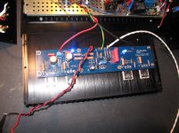
Some pictures are attached.
Problems :
- I soldered ZTX450, 550 and Led 2 in the wrong way --> I changed it. And now it work a little bit better;
- But, Q5 and Q6 are hot (normal), Q7 and Q8 remain cold. Input DC from PSU is -24 V / +24 V. The two leds are shinning. Output DC value is -20 V. The problem is the same for the two amplifier modules.
Do have any idea why Q7 and Q8 remain cold ?
Regards
biasing procedure - did you read beginning of the thread ?
negative DC offset on output means that lower mosfet is wide open , so you need to decrease resistance of R7' (trimpot)
if everything else is OK
negative DC offset on output means that lower mosfet is wide open , so you need to decrease resistance of R7' (trimpot)
if everything else is OK
Last edited:
OK. Initially did biasing procedure but i didn't turn the pot enough.biasing procedure - did you read beginning of the thread ?
negative DC offset on output means that lower mosfet is wide open , so you need to decrease resistance of R7' (trimpot)
if everything else is OK
Yesterday i tryed again and now all the mosfet are hot. But the DC output is very unstable +-1.5 V around 0. Is it normal ?
Thanks for your help
Attachments

that's too much +/-1V5
however , without any cables on input and without temp equilibrium (for that , case must be finished and lid on) it's hard to expect total stability
again - Iq and DC offset setting is iterative process , top lid on , as condition that amp gut is on steady tempreature
however , without any cables on input and without temp equilibrium (for that , case must be finished and lid on) it's hard to expect total stability
again - Iq and DC offset setting is iterative process , top lid on , as condition that amp gut is on steady tempreature
I don't know if its the picture and the wires playing tricks on my eyes but are you running the diodes to the wrong side of the board. I think you are not going through the caps and resistors.
Amp -
Place a simple 1K resistor acros the R8 LTP bias pad.
PSU -
Connection from diode bridges to PSU board is on the other side of the PCB.
Remove the output snubber (the small capacitor and resistor near the connection blocks.)
Place a simple 1K resistor acros the R8 LTP bias pad.
PSU -
Connection from diode bridges to PSU board is on the other side of the PCB.
Remove the output snubber (the small capacitor and resistor near the connection blocks.)
I don't know if its the picture and the wires playing tricks on my eyes but are you running the diodes to the wrong side of the board. I think you are not going through the caps and resistors.
I agree with you in that suspicion
looks like CRC is not used , wires from bridges going ditto to last C
Variac
Hey guys, almost done with my build. I wired up the boards and power supply yesterday and just need to finish my rear panel cutouts and then connect to the RCA connections and my speaker connections. My question is about turning it on for the first time. I have read about the light bulb method but I also have a variac called Dial A Volt. This thing is old, had it since I was a kid. If I used the variac, what should I look for if the power supply is not connected correctly? I was going to connect a volt meter to the V+ and another volt meter to the V-. Start turning it up and see if I get a voltage output. When should I start seeing a voltage output or better yet when should I stop turning it up if I don't see any voltage output? Or should I just stick with the light bulb method? Thanks for your help.
John
I used a variac for this one - I monitored the bias current as I turned it up (and looked for smoke!). Your power supply should probably be tested before you connect it to the amp board, though.
That is what I want to do, test the power supply first. Right now the wires going to the boards are not connected to the power supply board. I want to make sure I have the correct voltage first and nothing shorted.
I didn't use a variac for that - I just plugged it in and measured the output voltage. If you're worried about a short the bulb tester will do just as well - short and simple.
Bulb tester will usually limit current in case of a fault and keep things from burning up.
Plus if it lights up and stays lit, it's a very obvious indication of a fault! 😀
Plus if it lights up and stays lit, it's a very obvious indication of a fault! 😀
Thanks guys, that is what I need to know. I will use the bulb to test the power supply and then the variac when I hook up the amp boards.
- Home
- Amplifiers
- Pass Labs
- Aleph J illustrated build guide