Hi all,
Thank you so much for all of your guidedance and encouragement for me to finish this amp. I feel alot more confident in my abilities to build more subsequent Firstwatt amps in the future now! 😀
Aleph J is a very special amp. I spend some hours listening to it in the past days. I still have alot to discover of this amplifier. Only a few days is not enough to judge the amp sonic capability. It's definitely different from any other amps I used to listen in the past. It has much more punch for the power, soundstage is very big and large. I feel like my little room and speakers has not been able to unleash all the full potential of this amp just yet. I will let the amp settle and burn in a bit more and play around with some other preamp and speakers combination that I had to find the best match for AJ.
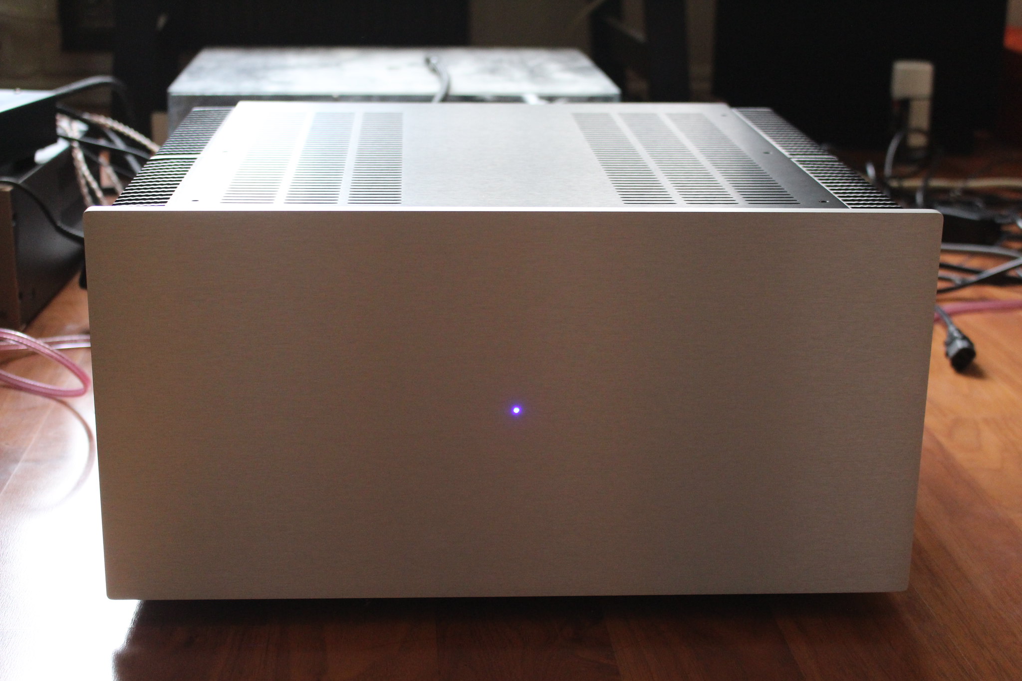
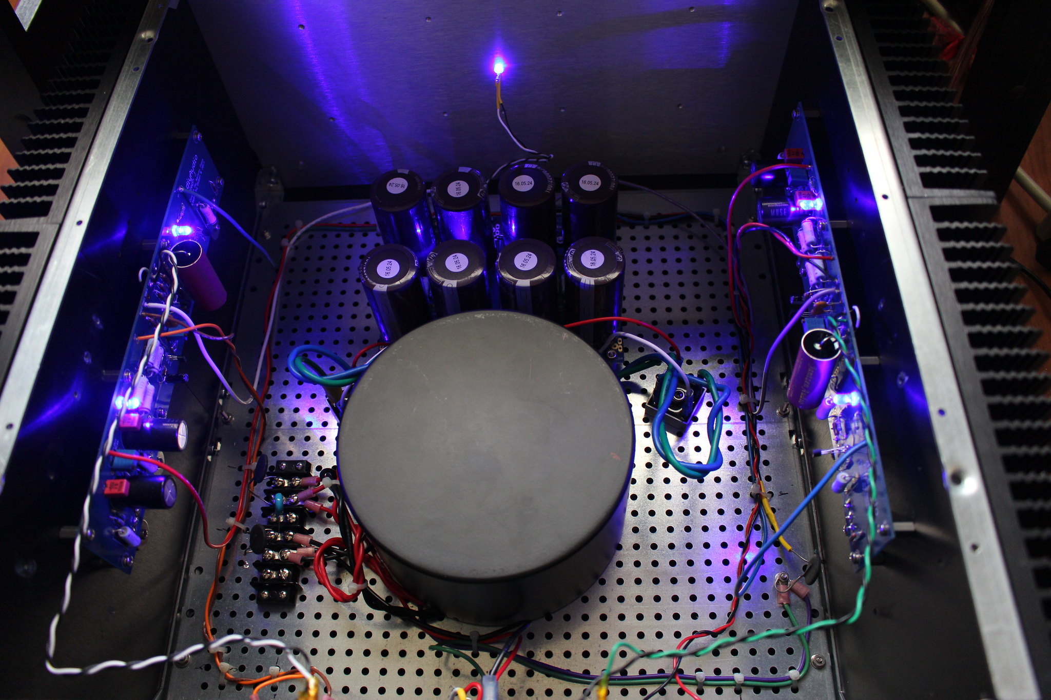
As promised, here are some of the photos of my finished work! Thank you Nelson for the great design and your contribution to DIY community. Thank you everyone once again for all of your valuable inputs especially JT 😀 (I think you know whom I refer to 😉 )


Most sincerely,
Tom
Thank you so much for all of your guidedance and encouragement for me to finish this amp. I feel alot more confident in my abilities to build more subsequent Firstwatt amps in the future now! 😀
Aleph J is a very special amp. I spend some hours listening to it in the past days. I still have alot to discover of this amplifier. Only a few days is not enough to judge the amp sonic capability. It's definitely different from any other amps I used to listen in the past. It has much more punch for the power, soundstage is very big and large. I feel like my little room and speakers has not been able to unleash all the full potential of this amp just yet. I will let the amp settle and burn in a bit more and play around with some other preamp and speakers combination that I had to find the best match for AJ.
As promised, here are some of the photos of my finished work! Thank you Nelson for the great design and your contribution to DIY community. Thank you everyone once again for all of your valuable inputs especially JT 😀 (I think you know whom I refer to 😉 )
Most sincerely,
Tom
Thanks Anand and Kazoo.
Yes. This is a 5U chassis. Transformer is 400 VA 20-0-20
Very nice build! What size trafo is that?
5U chassis?
Best,
Anand.
Yes. This is a 5U chassis. Transformer is 400 VA 20-0-20
DELA -
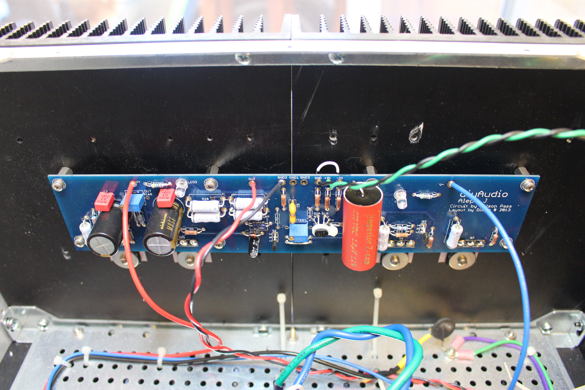
Connect -IN to GND, like this:
6L6, question for you on this comment. I am also using a shielded cable for my RCA input connection. So are you saying I should be running the shielded lead and the negative lead together to the ground location on the board? Is the negative location on the board only for XLR inputs? Right now I have the RCA positive going to + , the RCA negative going to - and the shield of the cable clipped off at the RCA but connected to the ground location at the board.
If the shield is open at one end, don't worry about it and leave what you have.
RCA (+) to +IN
RCA (-) to GND
Jumper -IN to GND
RCA (+) to +IN
RCA (-) to GND
Jumper -IN to GND
Hi Kazoo,
I believe if you are using RCA only, then -IN should be connected to GND
or your gain will be affected. (I've not tried it though since I use XLR on
mine.)
Thanks,
Dennis
I believe if you are using RCA only, then -IN should be connected to GND
or your gain will be affected. (I've not tried it though since I use XLR on
mine.)
Thanks,
Dennis
Yes, that's the whole point! 😀 😀 😀
Thanks 6L6, I will leave it as is, but do I still need the jumper from IN- to GND?
Thanks for your help.DELA -
Connect -IN to GND, like this:
It's a little bit better but not enought : the output DC remain unstable. Il thing that some components didn't like my first mistake (ZTX550, 450 soldered in the wrong way).
Before I start demounting parts I hope for some good adwise. The case is as follow: I am helping a friend of mine with his Aleph J build. He has done some serious mistake.
The powerpcb have V+, V-,V+ and V- ment to be connected to the two diode bridges.
There are two output terminals on each ends meants to go to two Aleph J PCB(+,0,-)
My friend have done this:
To the powerpcb he has connected + and - from the diode bridge to one of the power output terminal (+, zero and -, but of course without any zero connection)
From the second output terminal on the other end he has connected three wires to one Aleph J PCB (+,- and 0). Same mistake done on a power PCB number two.
This means that Aleph J PCB has been connected directly to the + and - on the diode bridge, but without any zero connection.
This faults has been fixed and the right connection from only one powerpcb has been done.
Bias is 400mV on both channels and offset very low. No problems to make ajustments.
But when starting up and slow down there are big bump in the loadspeakers. I think the amp is unstable as a result of the faults that has been done. But since both offset and bias work well, what components make the amplifier unstable. Is it Q1A, Q1B, Q2 and Q3???
Eivind S
connect dummy load (4 to 8R ) on output and try to measure what's that voltage bump when powering on
put few pictures here , it could help too
put few pictures here , it could help too
The dummy, how "big": 3W, 5W or 10W. Measure voltage bump, where? Sorry that I need explanation with a "teaspoon". This is new to me.
I will take some photos tomorrow.
Eivind S
I will take some photos tomorrow.
Eivind S
3W is enough , you can make that of several appropriate valued smaller (weaker) resistors in parallel
measure with voltmeter (fast eyes or hold function ) , connected on same place where dummy load is - speaker terminals
measure with voltmeter (fast eyes or hold function ) , connected on same place where dummy load is - speaker terminals
I found the "sinner" to most of the "bomp" problem. I tried go outside the soft start pcb and the bomp disappear when start up. But when turning down there is still a bomb, but not as load as before all changings. I have tried to measure each loadspeakerterminals with at 10 ohm 3w resistor when turning on and down. Not easy to read, but I measured approx. 150 mV both with on and off. Very fast this measurements went down to almost "nothing" (less than 1mV).
Eivind S
Eivind S
with speaker - describe how much excursion woofer is having , when powering On and powering Off ?
I use UPC1237 based relay board to avoid on / off thump for horn drivers that are DIRECTLY connected to AJs in my active setup. Works well and I don't hear any degradation in sound. I'm not sure if UPC1237 based relay can handle the most serious DC accident with Aleph J. Any opinion?
New Assembled UPC1237 Mono Speaker Protection Board | eBay
New Assembled UPC1237 Mono Speaker Protection Board | eBay
I only mean to help here...
My solution to the turn on or off thump with my Aleph J is a pair of switches at the speaker terminal. I leave them in the disconnect position. Turn on amp (no connection, no thump) engage speaker connection. Smile, it's perfectly quiet. The turn off sequence is to disconnect speakers with the switch then power down. Repeat.😉
My solution to the turn on or off thump with my Aleph J is a pair of switches at the speaker terminal. I leave them in the disconnect position. Turn on amp (no connection, no thump) engage speaker connection. Smile, it's perfectly quiet. The turn off sequence is to disconnect speakers with the switch then power down. Repeat.😉
- Home
- Amplifiers
- Pass Labs
- Aleph J illustrated build guide