Nelson says to use the slow in Class-A PSU. I like them just for the convenience factor.
As for your caps, use whichever fit better. I personally would save the 50V caps for a project that needs the higher voltage rating. Don't forget the inrush suppressor, those are all big caps.
As for your caps, use whichever fit better. I personally would save the 50V caps for a project that needs the higher voltage rating. Don't forget the inrush suppressor, those are all big caps.
We had this conversation with you, 6L6 🙂. I just took and tried ultrafast... I can tell you I liked the better, for my taste they give a quieter background 🙂. So I think I will be using them, at least for a while 🙂
I have both. I like both. I have two power amp projects in the works currently, one will use high-speed discretes, the other monolithic slow bridges. There is no single, correct answer.
😀
😀
Why do you say overkill of capacitance? I used 0.4f per channel on f5Tv2 and all my FW amps are using 0.4f for a mono PSU setup... As one wise man told me: Whatever makes you sleep better, right ZM? 🙂
cos 6 x 150.000 µF is 0.9 F and you'll agree that is quite more than 0.4

I'm planning to use 6x 150.000uf/35v per channel (monoblock)
PKI, more isn't always better. Did you make some measurements or at least use
PSU designer?
Believe me, I love big PSUs. I have 250 mF each channel on my AJ. That definitely
makes no poor PSU (it's also CRCLC with a shielded 500 VA toroidal). Problems raise
with capacitance though.
BTW, for diodes read this: http://www.diyaudio.com/forums/solid-state/12539-high-speed-diodes.html
Thank you all for great answer.
As i read from pass article :
For the caps :
================================
Bigger and heavier is better. Bigger transformers and wires load down less. Big capacitors hold more charge.
Is there such a thing as too big? Certainly there are diminishing returns as we get bigger. When a transformer is delivering 1 watt to a preamp circuit, going from a thousand watt rating to two kilowatts isn't going to buy you much improvement. This consideration is not much of a deterrent to the average audiophile, however.
==================================
I liked the word "diminishing return"
And i agree with it, value for money.
Big is better, but not equal for the value we get.
As for me, I am not buying more caps. I use those big can caps just because I have it before.
For the rectifiers:
=================================
Yeah, sure, rectifiers are important, after all, the AC has to get converted to DC, but I don't like the fast recovery types that some audiophiles have raved about. Fast recovery means that they withstand many amps and volts in a tenth of a few nano-seconds, something we don't see very often on the old 60 Hz AC line. They are essential element in switching power supplies, but for regular "linear" power supplies, I much prefer SLOW diodes, and we create them by placing small capacitor circuits across the diodes, which greatly reduces radiated noise.
==============================================>
This is very helpfull information.
But still, no explanation for the impact to audible.
Maybe it is measurement in tools vs audible(in ear)
I just think if caps are reservoir (and we have a very big reservoir) then we need a better and faster tools to get the water filling up the reservoir faster.
But I am not sure rectifiers have Related to this problem.
But I am not sure rectifiers have Related to this problem.
cos 6 x 150.000 µF is 0.9 F and you'll agree that is quite more than 0.4
PKI, more isn't always better. Did you make some measurements or at least use
PSU designer?
Oh, I am ashamed and humiliated now! 🙂
I know I know. I always think of a music as of modulated power voltage. I know about importance of measurement. Unfortunately, at the moment I do not have much test equipment for proper measurements.
Thanks for the link, I will read it!
PKI, search for PSUD2 (PSU designer) - it's freeware !! Results are often stunning. 🙂
This NP article is a buying guide for commercial equipent, not a design guide.
This make a huge difference.
The truth is, most commercial equipment comes with moderate PSU capability.
The main problem besides cost is the vast inrush current. For 0.9 F (900.000 µF)
you need tough rectifier diodes (+ heatsinks) and a soft start circuit to avoid
blowing fuses and rectifier damage.
Thank you all for great answer.
As i read from pass article :
For the caps :
================================
Bigger and heavier is better. Bigger transformers and wires load down less. Big capacitors hold more charge.
Is there such a thing as too big? Certainly there are diminishing returns as we get bigger. When a transformer is delivering 1 watt to a preamp circuit, going from a thousand watt rating to two kilowatts isn't going to buy you much improvement. This consideration is not much of a deterrent to the average audiophile, however.
==================================
I liked the word "diminishing return"
And i agree with it, value for money.
Big is better, but not equal for the value we get.
As for me, I am not buying more caps. I use those big can caps just because I have it before.
For the rectifiers:
=================================
Yeah, sure, rectifiers are important, after all, the AC has to get converted to DC, but I don't like the fast recovery types that some audiophiles have raved about. Fast recovery means that they withstand many amps and volts in a tenth of a few nano-seconds, something we don't see very often on the old 60 Hz AC line. They are essential element in switching power supplies, but for regular "linear" power supplies, I much prefer SLOW diodes, and we create them by placing small capacitor circuits across the diodes, which greatly reduces radiated noise.
==============================================>
This is very helpfull information.
But still, no explanation for the impact to audible.
Maybe it is measurement in tools vs audible(in ear)
This NP article is a buying guide for commercial equipent, not a design guide.
This make a huge difference.
The truth is, most commercial equipment comes with moderate PSU capability.
I just think if caps are reservoir (and we have a very big reservoir) then we need a better and faster tools to get the water filling up the reservoir faster.
But I am not sure rectifiers have Related to this problem.
The main problem besides cost is the vast inrush current. For 0.9 F (900.000 µF)
you need tough rectifier diodes (+ heatsinks) and a soft start circuit to avoid
blowing fuses and rectifier damage.
Last edited:
The main problem besides cost is the vast inrush current. For 0.9 F (900.000 µF)
you need tough rectifier diodes (+ heatsinks) and a soft start circuit to avoid
blowing fuses and rectifier damage.
Okay I got it. Thanks.
use them all
CLC or CRC
smaller then bigger
So if I have an equal number of 22,000uF and 10,000uF caps for a CRC, it's best to use (2 x 10kuF) -> (R) -> (2 x 22kuF)? (For an aleph-j)
I played around with the duncan amps tool and tried 3 permutations. I thought it was marginally better to have the high caps first. But I'm far from sure I looked at it correctly and I'm sure zen mod is smarter than a piece of software. 😀
every software is just smart as man using it
that includes Mighty ZM too , who is pretty dumb regarding any software
however - look at voltage and current in xformer and rectifier , not just on end of PSU
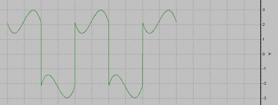
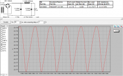
If I tell you that my next (proper ) amp will have current through xformer as attached , while needing 33Vac secs for 22Vdc@2A2 , without any sort of active regulation , what you'll think ?

that includes Mighty ZM too , who is pretty dumb regarding any software
however - look at voltage and current in xformer and rectifier , not just on end of PSU
If I tell you that my next (proper ) amp will have current through xformer as attached , while needing 33Vac secs for 22Vdc@2A2 , without any sort of active regulation , what you'll think ?
Attachments
every software is just smart as man using it
that includes Mighty ZM too , who is pretty dumb regarding any software
however - look at voltage and current in xformer and rectifier , not just on end of PSU
If I tell you that my next (proper ) amp will have current through xformer as attached , while needing 33Vac secs for 22Vdc@2A2 , without any sort of active regulation , what you'll think ?
I hate tests, my head hurts, this is stretching my abilities which is good. Looks like if you were to invert the negative part, you'd end up with a slightly asymmetric sine wave that has a +2 DC offset. Am I on the right track? Why is the Vdc lower than the Vac - I thought it should be 1.4 higher before losses.
1.4 only for unloaded or lightly loaded PSU-filter
I'm going to use choke input filter , that's why resulting DC voltage is lesser than secondary (AC) voltage
play with PSUD more , you'll learn much that way
I'm going to use choke input filter , that's why resulting DC voltage is lesser than secondary (AC) voltage
play with PSUD more , you'll learn much that way
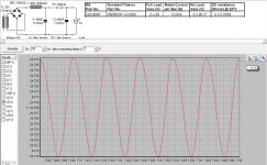
Tried to play with PSUD2, need your suggestion which one is favourable for dual mono configuration, pro & cons analysis will be much appreciated:
- CLC using 2x18V 225VA
- LCRC using 2x25V 500VA
for C6&C7, anyone try MKC type instead of MKP?
- CLC using 2x18V 225VA
- LCRC using 2x25V 500VA
for C6&C7, anyone try MKC type instead of MKP?
Attachments
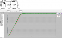

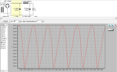
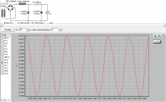
simulate for 50mS after delay of 7S
simulate after reporting delay of 0S only for startup check-up
simulate after reporting delay of 0S only for startup check-up
attached simulation results as ZM advise (previously i was confused with those 2 timing options). am I correct to put I meter @2A? I am using talema encapsulated datasheet information on this simulation. it seems that CLC gives better result as graph shows
Attachments
right click on xformer - edit - click on button right of source res , fill in upper 4 fields
for effective internal resistance (impedance) of xformer , you need both voltages and Rdc of (both) primary and secondary
that's why I said that Ri of xformer looks too low
F1 is magic button in PSUD
for effective internal resistance (impedance) of xformer , you need both voltages and Rdc of (both) primary and secondary
that's why I said that Ri of xformer looks too low
F1 is magic button in PSUD
- Home
- Amplifiers
- Pass Labs
- Aleph J illustrated build guide