
Thank you for the information. I have the MOSFETs and JFETs already, so all I need are the 550/560s.
I should have been more clear...
The store sells the ZTX parts in their kits specifically for use in the positions you noted. 🙂
Edited to add - I acknowledge that doesn't answer you direct question about the ratings for the parts you suggested. I was only offering one other alternative, if you happen to have ZTX parts available to you.
The kits are $60 plus shipping, and include parts I already have. The parts I need are less than a buck apiece. I support the store when I can, but I can't justify the expense in this case.
Sorry... I should type more thoroughly...
I'm not suggesting that you buy a full kit.
You were asking about a certain set of parts. I was offering another alternative for the parts and showing their validity for use in this application because they're sold by the store for direct use in those positions on that PCB for that amp.
What I'm suggesting is that if ZTX parts are available to you... then you can maybe get those (from any source you choose) instead of the BC parts you're considering.
Check pinout for both, but you may know this. Not sure how the boards are set up or if you're using "store" boards.
Edited b/c my spell check is ... grrrrr.
You're fine. I'm the one who isn't being clear. The ZTX550 aren't available either. Sorry for the confusion.
What's interesting is that Mouser has plenty of BC560s and ZTX450s.
What's interesting is that Mouser has plenty of BC560s and ZTX450s.
Thank you ZM. Why do you suppose the BOM specs the BC550C classification? Is the higher hFE an important feature or just a "better versus good enough" thing?
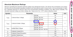
If you look at one of the datasheets which lists the entire BC54x/BC55x family of NPN devices, like the Fairchild datasheet in the screen capture attachment, you'll see there is a member of the family with higher voltage ratings than the BC550.
If you check that device on octopart.com {and BE SURE to click "Show All" in the bottom left corner} , you'll discover there is plenty of product on the shelf today (link), ready to ship immediately.
If you check that device on octopart.com {and BE SURE to click "Show All" in the bottom left corner} , you'll discover there is plenty of product on the shelf today (link), ready to ship immediately.
Attachments
In that case why not just use these? They have different pinouts from each but you'll be fine if you follow the designations on the PCB for Q2, Q3 and Q4.What's interesting is that Mouser has plenty of BC560s and ZTX450s
The kits are $60 plus shipping, and include parts I already have. The parts I need are less than a buck apiece. I support the store when I can, but I can't justify the expense in this case.
@Zen Mod @Dennis Hui :
Updating you on QA process. Matched IRFP240 MOSFETs installed both channels. Looked over components and wiring once again per schematic (from the beginning of this thread + store PCBs). Observations:
ALSO - I am running BC327 instead of ZTX550. I do have the orientation correct And in one channel put in a new one for good measure, the one I extracted tested good.
Updating you on QA process. Matched IRFP240 MOSFETs installed both channels. Looked over components and wiring once again per schematic (from the beginning of this thread + store PCBs). Observations:
- Making plenty of heat but not overheating
- LED Q2 not illuminating. New ones mounted tested and verified polarity. Odd.
- Power supply consistent both channels at 26.1V
- Both channels read 5V offset and .5V bias. How weird is that????
ALSO - I am running BC327 instead of ZTX550. I do have the orientation correct And in one channel put in a new one for good measure, the one I extracted tested good.
https://www.diyaudio.com/community/threads/aleph-j-illustrated-build-guide.241729/post-7398301
@Zen Mod
You may be on to something. I have a 2K pot for R7 and don't understand what should be done for R7' Nothing there now
Please instruct me

@Zen Mod
You may be on to something. I have a 2K pot for R7 and don't understand what should be done for R7' Nothing there now
Please instruct me
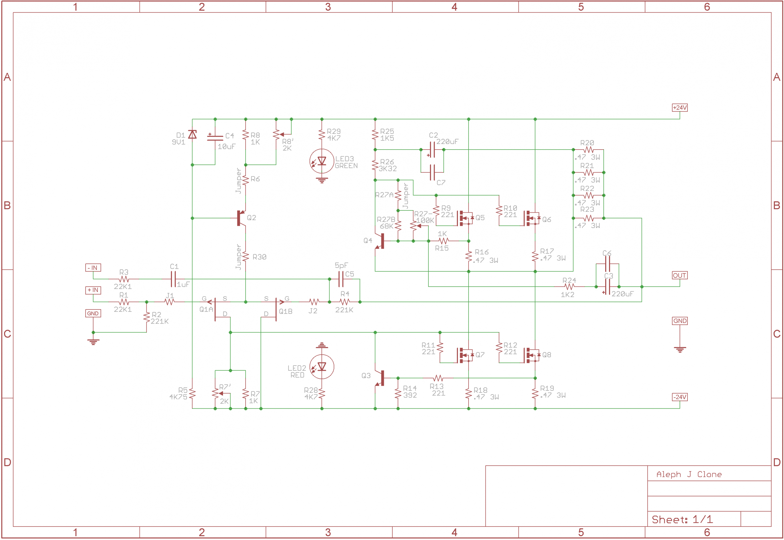
I presume there is jumper in R6 position
so input LTP CCS Q2 id programmed for current as (9V1-0V65)/1K=8.45mA
means that available current through R7 is half of that = 4.225mA
if we assume, say, 800mA as Iq for one vertical mosfet pair, that means voltage sag across source resistor of 0A8*0R47=0V376
taking in account that output mosfet Ugs need to be in +4V range to keep it open, adding 0V376 on top of that, we have sum of 4V375 as voltage between (say) Q7 gate and negative rail
so, voltage sag across R7 (2K trimpot) needs to be exactly that - in range of 4V375
let's deduce what value of R7 trimpot we need to set to have 4V375, with 4.225mA flowing through
4V375/4.225mA=1035Ohms
conclusion - 2K must be enough to cover needed range of resistance for R7
ok - ground both negative and positive inputs
no load at output
connect DVM No.1 across R18
connect DVM No.2 across speaker output terminals of same channel
power on
set reading of DVM No.1 with R27 trimpot to have approx. 400mV
now try to set reading of DVM No.2 with R7 to have closest to 0mV
as amps is heating up, correct one and/or another
when amp is fully heated/in temp. equilibrium, do final adjustments
https://www.diyaudio.com/community/threads/aleph-j-illustrated-build-guide.241729/post-7398338
I can get the bias to 400mV.
However, with the offset pot cranked fully clockwise, offset can only get to 4.63V, both channels behave the same
EDIT - swapped DMM's might be in business!
EDIT #2 - So strange now offset back up to 4.63V! For awhile both read close to 0
I can get the bias to 400mV.
However, with the offset pot cranked fully clockwise, offset can only get to 4.63V, both channels behave the same
EDIT - swapped DMM's might be in business!
EDIT #2 - So strange now offset back up to 4.63V! For awhile both read close to 0
Last edited:
- Home
- Amplifiers
- Pass Labs
- Aleph J illustrated build guide