Essentially your negative supply voltage is 0 volts. Do you have separate negative power supplies in addition to your positive power supplies? Please show an overall picture showing your complete power supply. Just a wild guess.

Yeah... one would assume the rails were okay.... There goes that saying.... Assumption... the mother of all fu@$up$
On a lark, I pulled an AJ sim and stuck -0.1V on the negative rail and got 4-ish volts DC offset. 🙂
@JKiriakis : It's clear now that you need to rework your PS. As a start, please have a look at the power supply schematics from post #1: https://www.diyaudio.com/archive/gallery/data/500/medium/F5PSUschematic.jpg
@JKiriakis : It's clear now that you need to rework your PS. As a start, please have a look at the power supply schematics from post #1: https://www.diyaudio.com/archive/gallery/data/500/medium/F5PSUschematic.jpg
Thanks lads for weighing in. I had two thermistors going from each of the last PS cap cans negative terminals to ground. Removed those, and now have equal Voltage out of each cap can measured to ground, 1/2 of the rails voltage per terminal. Symmetric.
Major success in now offset resolved both channels at less than 1mV. Bias steady at 400mV
Do I still need to rework my PS? I will upload a schematic of the PS in its existing state next.
Also - it doesn't play music. Yet. Powered down, connected known good source and speakers, another issue to solve somewhere.
You need to combine the two supplies into one, and use it to power both channels. See the PS schematic that Dennis referenced in post #9,484.
post schm here in post and talk about
significant amount of errors is due to misunderstandings, when speaking of forum correspondence
significant amount of errors is due to misunderstandings, when speaking of forum correspondence
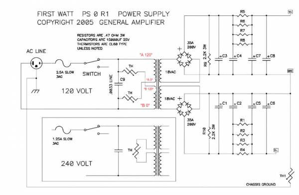
Schematic: First Watt PS
Yes, V+, Ground, V- to both amplifier boards.
Schematic shows CRC. You can keep your CRCRC.
Yes, V+, Ground, V- to both amplifier boards.
Schematic shows CRC. You can keep your CRCRC.
Progress - Reconfigured PS per above schematic. Heated up the amp, impressive how hot it gets! (4U 300)
Biased at 396mV, offset ~ 1mV.
It Plays Music!
Still some cracklies related to the input wires. 23 AWG has this funny clear insulator inside sheath, and I suspect some of that may be remaining.
Thank You All
Biased at 396mV, offset ~ 1mV.
It Plays Music!
Still some cracklies related to the input wires. 23 AWG has this funny clear insulator inside sheath, and I suspect some of that may be remaining.
Thank You All
@Extreme_Boky
appreciated. Not unexpectedly, and called out by @Zen Mod , hum is present. I will tidy up the PS and add your 10R ground lifts, ordered the resistors.
appreciated. Not unexpectedly, and called out by @Zen Mod , hum is present. I will tidy up the PS and add your 10R ground lifts, ordered the resistors.
Brief update: installed 10R ground lifts at junction where PCB ground wires meet last cap cans. Yes, completely eliminated buzz/hum as informed by other DIY posts.
However, the shift introduces a rather sharp audible high pop on startup and increases the thump on shut down. I will uninstall and work further on PS and input conductor routing, preferring a little noise to big noises.
With the 10R's in place and ears directly next to speakers, only the slightest wispy wavy sound may be detected.
Burning in now, quite a good sounding amp. With it's heat production, ordered a 140mm AC Infinity fan (Amazon $15). Completely surprised to the upside with the product, shipping material, and literature material enclosed. Company based in City of Industry (SoCal). So pleased I ordered another identical unit and its associated USB power block (they are designed and wired to daisy chain.
Initial plan was Babysitter, now, with one unit sitting on its silicone feet resting on the left side cover vents, I will first experiment with having both fans drawing air up and out.
Uninstalled the 10R ground lifts. Shortened those leads from PCBs. Reverted to slight hum/buzz. Pulled input RCA cables, dead silent. Discovered with B1K, the Aleph J is noisier than with Superphon Revelation, so back in the chain that preamp goes. If I revert to B1K will need to convert to XLR balanced input or another balanced pre / buffer. Or not, it's really not so bothersome. I just got used to dead silence between tracks.Brief update: installed 10R ground lifts at junction where PCB ground wires meet last cap cans. Yes, completely eliminated buzz/hum as informed by other DIY posts.
However, the shift introduces a rather sharp audible high pop on startup and increases the thump on shut down. I will uninstall and work further on PS and input conductor routing, preferring a little noise to big noises.
With the 10R's in place and ears directly next to speakers, only the slightest wispy wavy sound may be detected.
Burning in now, quite a good sounding amp. With it's heat production, ordered a 140mm AC Infinity fan (Amazon $15). Completely surprised to the upside with the product, shipping material, and literature material enclosed. Company based in City of Industry (SoCal). So pleased I ordered another identical unit and its associated USB power block (they are designed and wired to daisy chain.
Initial plan was Babysitter, now, with one unit sitting on its silicone feet resting on the left side cover vents, I will first experiment with having both fans drawing air up and out.
View attachment 1194118
I did not notice any "audible high pop" on start-up, or any difference in thump when powering the amp ON / OFF, with and without the ground lift resistor. The one thing that affects the thump is the quiescent current... more Iq => louder the thump.
I think it was reported that even with RCAs and ground lift resistor configuration, the buzz was gone when choke or additional PS capacitance was used.
Just for your information, my initial build was single-ended configured, with a ground lift resistor. I still had a very slight hum coming from the bass driver... but only with my ear very close to the driver. Standard build, single toroid and single PS PCB, a total of 22,000uF / 35V x 8 capacitance.
Things changed for the better when I reconfigured the amp for XLR inputs and switched to a true balanced-out DAC. I did not change anything else, apart from carefully re-wiring the common returns and improving the PS PCB grounding. There is no buzz, hum or hiss... even with my ear close to the bass driver or tweeter (86dB (in)efficient speakers). It is like... my amp is not powered up.
https://www.diyaudio.com/community/threads/aleph-j-illustrated-build-guide.241729/post-7404352
Helpful and good to know. Further to my remaining issue:
Also - how hot should the thermistors get (the two directly connected to my transformer, hot enough to burn your fingers)?
Helpful and good to know. Further to my remaining issue:
- Right channel has a pronounce buzz, less so on the Left. I tried to add back the 10R ground lift, didn't help so omitted it.
- Source not the issue (either preamp, DAC, CDP, turntable, tuner)
- Shorting inputs kills the buzz 🙂 As does muting the preamp.
- Just A/B'd it against my EL84 SEP amp. The J sounds killer. I want to perfect it.
Also - how hot should the thermistors get (the two directly connected to my transformer, hot enough to burn your fingers)?
- Home
- Amplifiers
- Pass Labs
- Aleph J illustrated build guide