if black probe of DVM No.2 is on black speaker terminal, output offset is positive or negative?
then nothing is logical
if offset is positive, that means more voltage is across Q7 & Q8 than it is across Q5 & Q6, so Q7 & Q8 must be hotter than Q5 & Q6
if offset is positive, that means more voltage is across Q7 & Q8 than it is across Q5 & Q6, so Q7 & Q8 must be hotter than Q5 & Q6
if you made it properly, you're having symmetrical unloaded rails and also symmetrical loaded rails
though, I can't say did you wire it properly, to have least amount of hum and ripple
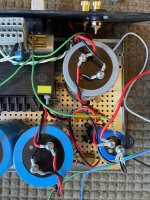
what I can see on that picture, that's most likely very far from optimal wiring
though - that is separate issue per se, first you need to solve what's wrong with setting of amp
you have DVM, confirm rails voltage
though, I can't say did you wire it properly, to have least amount of hum and ripple
what I can see on that picture, that's most likely very far from optimal wiring
though - that is separate issue per se, first you need to solve what's wrong with setting of amp
you have DVM, confirm rails voltage
https://www.diyaudio.com/community/threads/aleph-j-illustrated-build-guide.241729/post-7398484
Rails voltage 26.1 both channels. This power supply was used in my ACA dual parallel amp and despite the sub-optimal wiring produced no hum, equally quiet to ACA stereo w/ 2 bricks. Only change made to this supply since the last dual parallel amp was to increase one of the power resistors from 0R5 to R1, which dropped the rails by 3V.
Absolutely agree the priority is the offset issue and imbalance between the MOSFETs side to side. Working through the components I suspect the R7 pots will pull then today. I have another set of new 2K units in stock.
Grateful for your tremendous persistent support.
@Zen Mod
Your diagnostic mind hard at work! Results: (L) = left channel (R) = right channel
Zener (L) 9V06 (R) 8V99
Q2/R6 to R29 (L) 8V49 (R) 19V24 I am going to guess this is the telltale to our offset problem
R16 (L) 402mV (R) 400mV Bias holds well, I set yesterday at full temp at this level, same values just now
Offset (L) 4V76 (R) 4V76 I had set R7 at R1k. Turning pot counterclockwise yields fast high voltages, other way increasing resistance has little effect
R19 (L) 407mV (R) 400mV
R7 (L) 4V75 (R) 4V72
What say you Mighty?
L channel everything sounds OK, except output offset, and that's enough of wrong; I don't know what can be wrong if everything is done by, say, schematic I edited
R channel - 19V24 across 1K (R8) means something fishy with with Q2,
I can't think of nothing else than - replace all small bjt transistors, taking care of their pinout , and try again
btw. I don't care for set value of R7; I care for offset and Iq, I don't care too much what ohmmeter is saying for trimpots
nor I care too much for trimpt CW or CCW , I can't remember that even for my own pcbs; I'm simply looking at DMM to see am I turning it in proper direction
you have some systematic error common for both channels; again, I can only suspect that's issue with small bjts - maybe you did damage while soldering
did you confirmed value for both rails with DVM?
I changed all the bjts on the left channel. The ones that came out checked closely to the replacements. On the right I changed Q2 with a fresh BC327, which resolved the Q2 - R29 issue it now measures 8V5 matching the left channel measurement.
And as you've said, no effect on the offset problem. Still 4V72
both rails 27V5
And as you've said, no effect on the offset problem. Still 4V72
both rails 27V5
Correct 2k trim pot in place of R7. I lifted the original it measured fine but replaced it with a new one (measured).
Would it be of value to measure 27.5v output from last PS cap to ground both + and - side of the cap? I wonder if my PS is causing the offset imbalance, as the power resistors reside only between the positive poles of
the cap cans.
Would it be of value to measure 27.5v output from last PS cap to ground both + and - side of the cap? I wonder if my PS is causing the offset imbalance, as the power resistors reside only between the positive poles of
the cap cans.
well, I hope you have positive rail, GND, and negative rail - all 3 connected to amp pcbs
and that rails are of same value, ref. to GND
I mean - that's the very start to make an amp
and that rails are of same value, ref. to GND
I mean - that's the very start to make an amp
I do have all 3 wires connected to amp pcbs.well, I hope you have positive rail, GND, and negative rail - all 3 connected to amp pcbs
and that rails are of same value, ref. to GND
I mean - that's the very start to make an amp
@Ben Mah I will remeasure all the source resistors.
This will make life easier (I also removed the resistors connected in parallel with the trim pots 🙂):

... fill in the voltage readings.... so that we can have a full picture; it'll help diagnose the problem.
... fill in the voltage readings.... so that we can have a full picture; it'll help diagnose the problem.
Circling back: Source resistors measure in mV left to right (L) 383, 386, 378, 380 (R) 380, 378, 378, 380. I didn't heat the amp up for this, but it doesn't appear there is a bad MOSFET.
Please note both channels exhibit the same error, 4V72 offset instead of 0V.
(L) Last + side of PS cap to GND = 27V26, - side = -99.8mV (R) Last + side of PS cap to GND = 27V38, - side -99.8mV
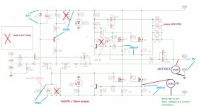
@Extreme_Boky thank you for your QA chart. Comparing it to @Zen Mod post #9468 jpeg above, you have in addition R24 to GND and measuring across Q4. I will do that and come back to you.
Please note both channels exhibit the same error, 4V72 offset instead of 0V.
(L) Last + side of PS cap to GND = 27V26, - side = -99.8mV (R) Last + side of PS cap to GND = 27V38, - side -99.8mV
@Extreme_Boky thank you for your QA chart. Comparing it to @Zen Mod post #9468 jpeg above, you have in addition R24 to GND and measuring across Q4. I will do that and come back to you.
It seems your negative rail is only about -0.1V. What's going on here?(L) Last + side of PS cap to GND = 27V26, - side = -99.8mV (R) Last + side of PS cap to GND = 27V38, - side -99.8mV
I think you should disconnect the amp boards and make sure you can get symmetric rails before continuing.
- Home
- Amplifiers
- Pass Labs
- Aleph J illustrated build guide