ZM / Dennis / Tungsten / 6L6 et al,Sorry, the source is the from the FW paper Practical MOSFET Testing for Audio, page 5, fig 4. It has an AC source in the schematic. Just want to confirm what that source is.
Aleph J boards 99% complete. I have 8 matched Onsemi 240s from Rthatcher.
Also have 20 Fairchild 044N10 from a single supplier yet to be tested and matched. Just assembled the little Amazon $16 9V multi tester expect testing easy.
Would you suggest I try to match the 044s?
If so any further advice? How to heat sink during the matching test etc?
And welcome your opinions on your chip of choice and why.
With Appreciation,
Jim
I'm banging my head on the wall....the left channel is back to misbehaving. It was worked out and sounding good until it start having a really loud hum. I checked offset and it was at -15.6V. When the amp is powered on, offset starts around +5V and drops around -15. The bias holds steady at 4.50. Any thoughts on what would cause the offset to drop like that?
Found economical torque thingies. $16 available in single ratings eg 0.9 nM or 1.0 etc. I have one on order and will report efficacy. Didn’t want to spend $100 to $300 for super fancywell, re-goop those you want, and it'll be handy to torque them all with torque-thingie, 0.9Nm
if not, try to be same gentle on all of them
Pa spoiled me, insisting, so I realized that having torque thingies for both M3 and M4 is very good for my OCD
https://www.hoffmanngroupusa.com/german-torque-screwdriver-tq-t-handle-automatic-triggering/

Thanks for the help so far guys. Sorry it took so long to get some pictures posted but life gets in the way sometimes. I took some measurements on both the good board and bad board to compare but not really sure what they mean. All measurements are from indicated point to signal ground. Working board has had pots adjusted for bias and offset, bad board pots still in centre position.
Point Good Bad
In + 240k 243k
In - 9M 16M
Q7 G 3M 2.6M
Q7 D 9M 16M
Q7 S 6.8M 7.4M
Q8 G 7.6M 2.5M
Q8 D 25M 4.1M
Q8 S 7.6M 1.5M
Q5 G 25M 2.0M
Q5 D 26M 1.2M
Q5 S 26M 4.7M
Q6 G 3.8M 4.7M
Q6 D 3.9M 4.9M
Q6 S 26M 4.6M
Q1A S 2.1M 2.2M
Q1A G 233K 222K
Q1A D 2.6M 3.0M
Q1B S 2.6M 2.7M
Q1B G 2.1M 12M
Q1B D 1.6M 3.6M
I am not sure what to make of this. I looks like all of the MOSFETs are toast. I did check to make sure none were shorted to the heatsink prior to the first power up. The zener diode in both boards measures the same. I am not finding any shorts to the heatsink when I poke around.
Attachments
In my previous post the columns did not show up very clearly. There are supposed to be three columns. First is point measured from, second it measurement on the good board, third is measurement on the bad board.
Thanks.
Dan
Thanks.
Dan
You guys are making me cautious about my retrofit process! I will be taking a week to check everything over one-more-time to make sure I have made no mistakes!
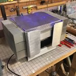
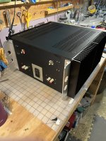
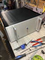
I've put my Aleph J into another case, a 5U, because I had hoped it to be stronger for shipping it to my new home... eventually. I picked a large case for heat sinking and for ease of transfer, it required less disassembly. I can recommend attaching some "handles" to the back plate so that standing the amp upright for fussing/assembly is easier and also to put the faceplate on before the back plate. What a bugger it is to fit the faceplate last! Further note that one must plan on buying "extra" bolts for the base plate to heat sink/sides, what was sent was inadequate. Anyway, it got done 🙂
I built my original 10 years ago (shown) then rebuilt it when it developed a connection/channel issue. Now it is in a conventional home even though it retains most of my first build concepts. I don't know if it is an improvement, let me know what you think ;-). I only hope it is going to survive crate shipment as the Aleph J is my first choice among many amps for the new home overseas 🙂
Attachments

Pretty darn cool Mad Max looking build in picture one.
😎
If you forced me to give some sort of light constructive criticism: Always Eleminate all sorts of screwy/pushy connection blocks whenever you can.
Always direct connect wire or soldered connection points. Less BS is more.
🙂
😎
If you forced me to give some sort of light constructive criticism: Always Eleminate all sorts of screwy/pushy connection blocks whenever you can.
Always direct connect wire or soldered connection points. Less BS is more.
🙂
New Aleph J build, first power up of left channel. Passed the dim bulb. Removed it, on to full power on left channel.
Rails are at 29V. Will hold bias at .35V
Can't get the offset to zero, best case .36V with R7 pot cranked fully clockwise.
LED on the right side of the board inop. MOSFETs on that side not generating any heat.
Next steps to diagnose? Thanks!
Rails are at 29V. Will hold bias at .35V
Can't get the offset to zero, best case .36V with R7 pot cranked fully clockwise.
LED on the right side of the board inop. MOSFETs on that side not generating any heat.
Next steps to diagnose? Thanks!
JeyDee, good constructive criticism;-). I DO build with more of a sense of order these days. I still build with terminal strips though as they make solid connection and make alterations, at least modular ones, possible. I do mostly tube amps. It sort of reverberated back into my solid state builds/rebuilds. 😉
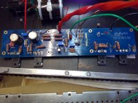
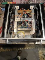
For this new form I wanted to keep the modules in tact, less tear down, less chance of screw ups 😎 The huge toroid transformer packed under the PSU board was moved and attached as a unit. DIYaudio boards fit almost perfectly into the heat sinks - I needed to make some support boards to support the loose hanging PCBs as in my early days I was less precise in my drill and tap. Connections to the back panel could be soldered but then removing the back panel would be a serious hassle. I could have used a DIYaudio board to handle the turn off thump/squeal but the switches on the front serve the purpose and who can justify MORE complexity, especially when you already have the bits and a tested solution? And I May have a "thing" for silver toggle switches...
After having gone through the two full days of work to transfer the innards even as intact as they were, into the kinda expensive case, I think the smarter move would be to just disassemble the original (Mad Max) looking version and transport it that way. I was worried about the joint between the very heavy heat sinks and the inner frame. It was weak, not the best solution I have ever come up with. 'Should have just shipped it in three parts. You just don't know until you try right?
Cheers!
@JKiriakis
post exact linkto/schematic you're using , clarify what you did with few positions were you have choices what to do, and specify polarity of DC Offset you're measuring
pics could help also to clarify said choices
post exact linkto/schematic you're using , clarify what you did with few positions were you have choices what to do, and specify polarity of DC Offset you're measuring
pics could help also to clarify said choices
@Zen Mod
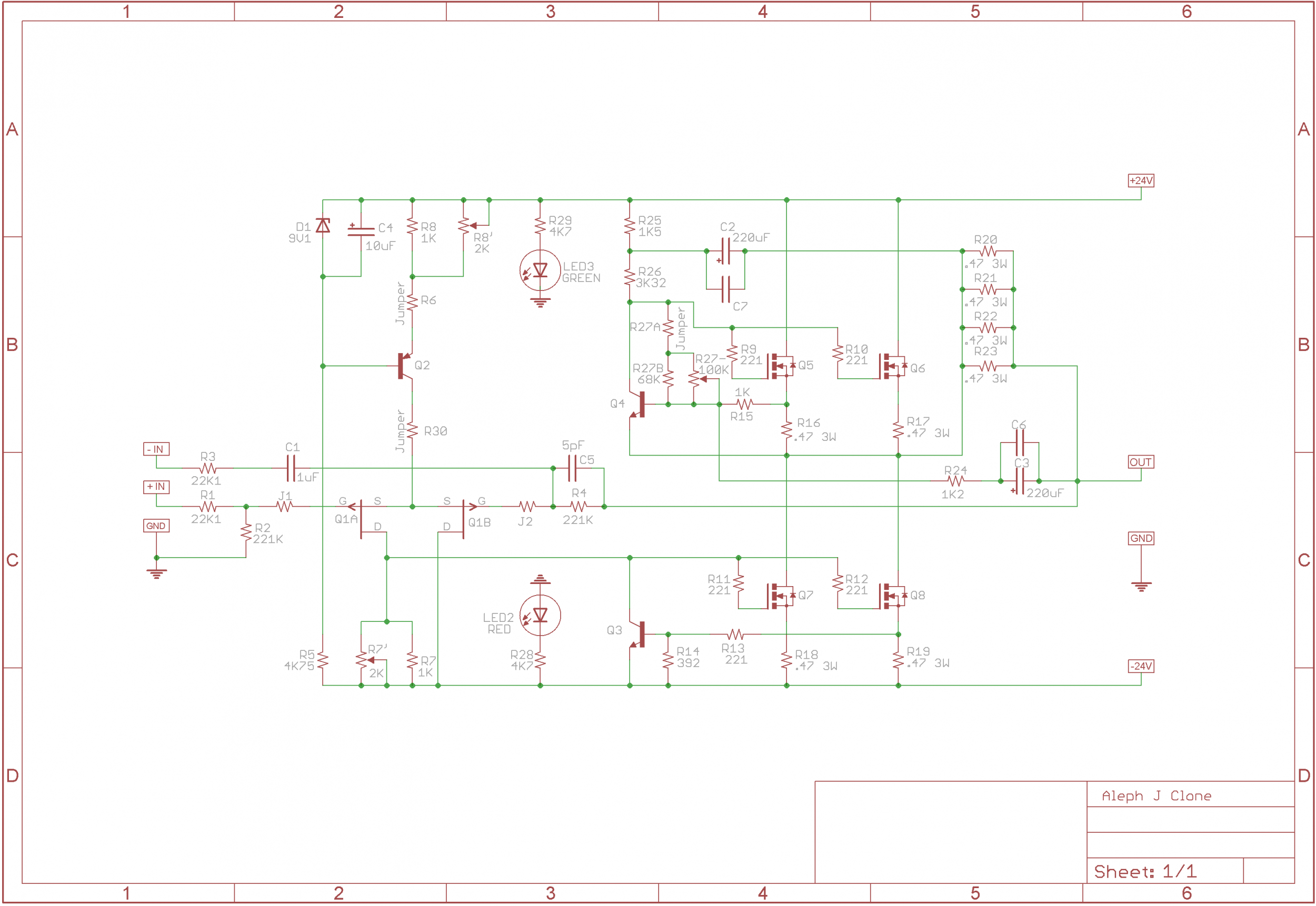
Schematic per the first post in this thread. https://www.diyaudio.com/community/threads/aleph-j-illustrated-build-guide.241729/
Re: choices (1) MOSFETs are Fairchild FQH44N10. Source was eBay, not sure if they are suspect though claimed by vendor as genuine. I do have a matched set of 240s from Rthatcher in stock. (2) Toshiba 2Sj74 quad matched from Punkydawgs (3) Q2 are BC327-40. This morning determined I had that one in backward having reviewed the datasheet vs. the 550. (4) R30 jumper is a 1/4w 200R (5) C5 is a 7pF mica which actually measured at 9.5pF vs. 5pF per schematic.
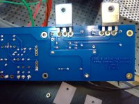
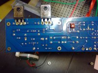
Seeing 29V at the rails this morning after rotating Q2. Still biases at .35V, but now the offset is -.4V (negative polarity) and the MOSFETs are not heating. Here are the boards before reorienting Q2, and prior to adding C5 and R30. Left channel only, I intend to resolve this one before attempting to power the right channel PCB. Thank you in advance.

Schematic per the first post in this thread. https://www.diyaudio.com/community/threads/aleph-j-illustrated-build-guide.241729/
Re: choices (1) MOSFETs are Fairchild FQH44N10. Source was eBay, not sure if they are suspect though claimed by vendor as genuine. I do have a matched set of 240s from Rthatcher in stock. (2) Toshiba 2Sj74 quad matched from Punkydawgs (3) Q2 are BC327-40. This morning determined I had that one in backward having reviewed the datasheet vs. the 550. (4) R30 jumper is a 1/4w 200R (5) C5 is a 7pF mica which actually measured at 9.5pF vs. 5pF per schematic.
Seeing 29V at the rails this morning after rotating Q2. Still biases at .35V, but now the offset is -.4V (negative polarity) and the MOSFETs are not heating. Here are the boards before reorienting Q2, and prior to adding C5 and R30. Left channel only, I intend to resolve this one before attempting to power the right channel PCB. Thank you in advance.
waiting for boys really versed in this pcb, even if from your explanation I'm expecting you got it OK
if Iq is 0V35 across 0R47 resistors, mosfets are heating, you probably just didn't wait enough to get them hot
now, if offset is negative, all you really need is to get it back fiddling with R7' trimpot ........ to "close" lower mosfets slightly
Seeing 29V at the rails this morning after rotating Q2. Still biases at .35V, but now the offset is -.4V (negative polarity) and the MOSFETs are not heating.
if Iq is 0V35 across 0R47 resistors, mosfets are heating, you probably just didn't wait enough to get them hot
now, if offset is negative, all you really need is to get it back fiddling with R7' trimpot ........ to "close" lower mosfets slightly
@Zen Mod -
https://www.diyaudio.com/community/threads/aleph-j-illustrated-build-guide.241729/post-7395074
Ran it for well enough time to heat MOSFETs, they are not heating. Bias still at 0V35, but now offset is +4V, clearly something is not right. If any of you with QA insight might help identify high priority areas where to look for failure based on your experience, it would be appreciated.
Meanwhile, having read this and the noob thread I will re-check components vs. schematic and start to test.
someone must decide what to believe; your words that mosfets are cold, or your saying that you're measuring 0V35 across 0R47 resistor
which means that you have 744mA through one mosfet pair, with two pairs means sum Iq is 1488mA
if there is a current and at least some voltage in rails, there must be heat
so, something is fishy - you either still have cooking glove on hand ....... or you don't know where to measure Iq .......... or battery in your DMM is shot
How were your mosfets matched?
Please measure and post the voltages across the four 0.47R source resistors R16, R17, R18 and R19.
Please measure and post the voltages across the four 0.47R source resistors R16, R17, R18 and R19.
@Dennis Hui
The mosfets currently mounted were not matched (44N10). I will make the measurements and report back.
ZM, hands are bare I have two DMMs and they're both reading consistently 🙂
Thank you Gents.
The mosfets currently mounted were not matched (44N10). I will make the measurements and report back.
ZM, hands are bare I have two DMMs and they're both reading consistently 🙂
Thank you Gents.
I'm trying to determine an acceptable substitute for the BC550C/560C BJTs since the 550Cs don't seem to be available from any reputable vendors. I've scoured the forum, and found that the BC549C/559C are similar, but they have a lower Vcbo and Vceo (30 volts versus 50 volts for the 550/560). Is there any issue with using them in the Aleph J for Q2,3,4?
Thanks in advance for your help.
Thanks in advance for your help.
Last edited:
- Home
- Amplifiers
- Pass Labs
- Aleph J illustrated build guide